 |
| Classic Performance Products |
| TCI bolt-in four-link Kit |
| By John Gilbert |
|
|
As a rule, it's pretty safe to say any major change
one might make to their truck's suspension would be to improve its handling
or set a lower stance. At the conclusion of shooting the tech feature gracing
these pages, we discovered a reason for changing a suspension setup that
never even occurred to us.
When Kevin Francis at KA Custom in Huntington Beach, California,
invited us to check out a TCI bolt-in four-link he was
installing onto a 1956 Chevy long bed pickup, we figured it would be a good
opportunity to pick up some new tricks from Kevin to pass on to Custom Classic
Trucks valued readers.
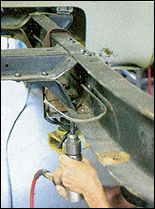
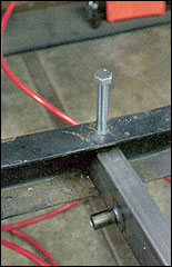
Sure enough, when the time came for Kevin to knock the
stock spring perches off the '56's frame, we learned a faster and easier
way to remove the hot rivets holding the perches. In the past, remov- ing
the rivets has always been one of those time-consuming chores we dread-
ed. Our standard procedure was to grind the head almost completely off and
then hammer a drift punch into the headless rivet. |
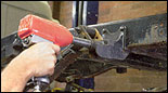
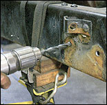
In the photos, notice Kevin used a body grinder mounted with
an abrasive wheel to cut (grind) X's deep into the head of the rivets. The
next step was to break out his trusty Snap-on air hammer (Kevin says Snap-on
air hammers work the best) equipped with a cold chisel attachment, then
knock the quartered head fragments off. The third and final step was to
switch the cold chisel attachment for a drift-punch attachment and hammer
the remaining hot rivet shank through the truck's frame and onto the ground
below. It was the minor details in Kevin's method that made short work of
an otherwise miserable task.
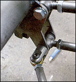
Correct us if we're wrong, but we believe this is the first
time the .subject vehicle of a four-link install has been a longbed Tri-Five.
When we asked Kevin if there was any reason why his customer chose a long
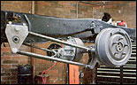
bed over a shortbed truck, he explained the guy was going to convert the
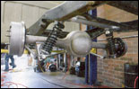
'56 pickup into a flatbed. Jumping to a conclusion, we surmised Kevin's
customer specified a four-link so he could lay the truck out on air bags,
making it much easier to load. |
Kevin said, Nope, it's going on coilovers After trying to
imagine every kind of mechanical advantage a four-link could offer, we were
stumped. Then it came to us: Since the truck was going to be a flatbed,
the guy was converting it to a four-link because the rear suspension would
be totally exposed, and he wanted his truck to look good after all, a short
dress needs nice legs.
Whatever the reason, installing TCI's bolt-in four-link is a
pretty straightforward proposition. Of course, these vehicles are around
50 years old, so due to wear and tear, each truck might present a slightly
different challenge when it comes time to bolt one on. |
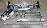 |
| 1.The 9-inch Ford rearend was supplied by KA Custom's customer.
Kevin welded on the differential mounting brackets, included with TCI's
four-link kit. This was the only welding necessary to install the kit. |
|
 |
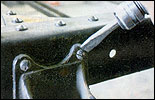
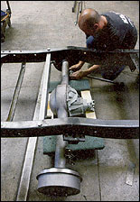
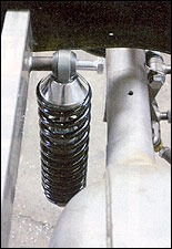
| 2. Kevin started by unbolting the truck's existing overload
shock absorbers. |
|
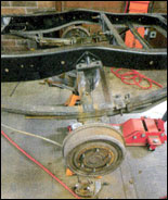 |
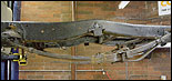
| 3. It's not hard to imagine why Kevin's customer didn't want
the original suspension left exposed under his custom flatbed project-it's
hideous. |
|
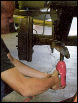 |
| 4. Next in line was to unbolt the U-bolts. Kevin started with
an air impact gun, but... |
|
 |
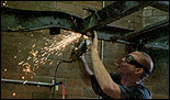
| 5 ...due to 50 years of rust, it was necessary to cut them
off. |
|
 |
| 6. With the drive-shaft and brake lines already disconnected,
removing the springs and shocks was all it took to remove the truck's rearend. |
|
 |
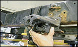
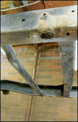
| 7. The leaf springs along with their perches were next to
be removed. |
|
 |
| 8. Kevin unbolted the springs from the front perch and rear
shackles. |
|
 |
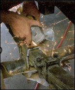
| 9. The fast way to remove the spring perches was to grind
X's into... |
|
 |
| 10..the heads of the hot rivets attaching the perches to the
frame. |
|
 |
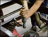
| 11. The chiseled them off with a cold chisel attachment on
an air hammer. |
|
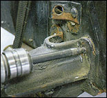 |
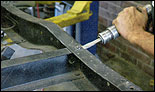
| 12. The final step was to use the air hammer with a drift
punch attachment. |
|
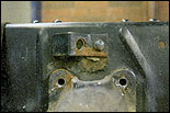 |
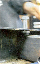
| 13. With the rivets driven out... |
|
 |
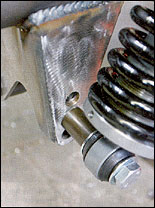
| 14 ...the spring perches were easily removed. |
|
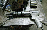 |
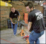
| 15. Kevin swears by his Snap-on air hammer sometimes, he just
swears. |
|
 |
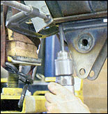
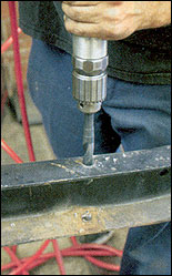
| 16. In order to mount the pickup point for the front of the
links, Kevin had to drill 5/8- inch holes into ihe framerail. |
|
 |
| 17. The third mounting hole for the bracket had to be drilled
vertically. |
|
 |
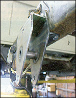
| 18. Kevin bolted the bracket into place, then used it as a
template to drill the 7/16-hole required to mount the top link bar into
place. |
|
 |
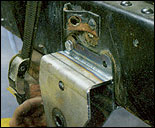
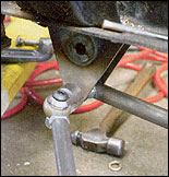
| 19. Upon mounting the front link bracket for the other side,
Kevin discovered there was an alignment problem caused by the old truck's
framerail. He used a C-clamp with a flat plate to compress the bracket into
alignment before he drilled the 5/8-inch bolt holes. |
|
 |
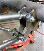
| 20. Here's the bracket bolted in place after Kevin aligned
the bolt holes. |
|
 |
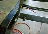
| 21. After the link perches were mounted, next on the agenda
was to vertically drill the frame-rails and install the TCI rear crossmember. |
|
 |
| 22. George at TCI likes to remove the smaller brace on the
left of the photograph to gain access. Kevin chose to leave the brace in
place either way seems to work ok. |
|
 |
| 23. Here, the crossmember is tapped into position. |
|
 |
| 24. Kevin dropped the two crossmember mounting bolts into
place... |
|
 |
| 25. Making sure to place a spacer on each side between the
TCI crossmember and the top framerails. |
|
 |
| 26. For the initial adjustment of the link bars, Kevin threaded
the ends in halfway... |
|
 |
| 27 ...then attached them to the brackets on the differential. |
|
 |
| 28. The coilover shocks were bolted on top of the TCI crossmember,
then... |
|
 |
| 29 ...bolled to the backside of the differential brackets.
(Note that there are three positions 10 place the bolls. Moving these bolls
lowers or raises the truck's ride height. |
|
 |
| 30. The last link to connect was the track rod. |
|
 |
| 31. The track rod (front) connected to the (front) right-side
lower link on the passenger-side frame bracket. |
|
 |
| 32. An outside view of the rear links with the track rod end
in place. |
|
 |
| 33. An inside view of the track rod rear mount. |
|
 |
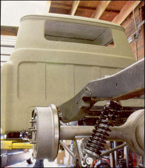
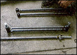
| 34. A left side view of the completed TCI bolt-in four-link
suspension. |
|
 |
| 35. A rear view of the completed TCI bolt-in four-link suspension. |
|
|
|