 |
| Classic Performance Products |
| 1949 Chevrolet - Back Surgery |
| By Kev Elliott |
|
|
|
Ever since I used a pair of C10 trailing arms with airbags
on a customer's car a couple of years ago, and was impressed with the ride
quality those long arms offered, I planned on using a pair on my '49 Chevy.
I even went so far as to scrounge a pair from my co-worker, Custom Classic
Trucks' Cody Wentz, when he upgraded his own truck.
Then, I got to talking with Danny Nix at Classic Performance
Products, and a plan was hatched to use my car to prototype a new bolt-in
trailing-arm kit for the '49-54 Chevys. This fit perfectly with my bolt-together
theme for the car, so I dragged the sorry-looking coupe over to CPP's Anaheim
facility. |
The stock closed drivetrain wasn't part of my plan, so I replaced
the stock rearend with a Currie Enterprises custom Ford 8-inch axle featuring
11-inch brakes, big-bearing Torino axle ends, new 28-spline axles, and 3-inch
axle tubes. I didn't feel a 9-inch was necessary in what will essentially
be a cruiser, albeit hopefully a long-distance one. Plus, space under the
car was at a premium, as I'd already C-notched the chassis and altered the
floorpan, and the smaller 8-inch pumpkin would offer more clearance. Since
I'd already modified the driveshaft tunnel to clear the stock enclosed driveline,
which ran down the center of the tunnel, I requested the axle from Currie
with the yoke centered and the pumpkin offset, too-another reason for making
the most of the space available. |
Opting for ShockWaves from Air Ride Technologies to provide
suspension, rather than the regular airbags I'd originally envisioned using,
meant this part of the install will differ from the production version of
CPP's kit (though the lower ShockWave mounts as shown here are available,
too), as my car has an additional 4 inches of suspension drop, thanks to
the C-notch. 'Bags and another crossmember will replace the ShockWaves on
the production kit, since a stock floorpan won't allow the height required
to fit 'em.
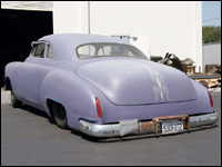
With all the pieces of the puzzle in one place, here's
how the Purple Pig went from having its stock axle swaying around on 6-inch
blocks and leaf springs to riding in style with long trailing arms and adjustable
air suspension carrying a 3.55:1-equipped live axle with brakes big enough
to haul the Chevy down from the speeds at which I usually travel. Hey, they're
cars, and I drive 'em like I do my daily. |
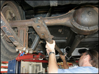 |
| Here's what I was replacing-the stock closed driveline, albeit
with lowering blocks and repositioned shocks, as I'd previously C-notched
the rear framerails and added a framework to accept airbags at a later date.
That date was now, only in the interim, Air Ride Technologies has introduced
the ShockWave, which is what I'll now be using. Before the guys at Classic
Performance Products removed the stock axle, one of their truck trailing
arms was offered up to determine the location of the prototype crossmember. |
|
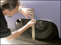 |
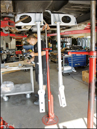
| With the car on the ground at ride height, CPP's Danny Nix
marked the centerline of the axle on a piece of tape on the fender. Yeah,
mind the paint, Danny! The measurement from the axle to the fender was also
noted as a datum for centering the new axle. |
|
 |
| Adjustable stands were placed under the axle and the pinion
yoke before the axle was centered in the car using the measurements previously
taken. The pinion angle was set to match the angle of the transmission tailshaft. |
|
 |
| Currie Enterprises provided a Ford 8-inch axle, supplied loosely
assembled and without brakes so we could attach the bracketry and return
it to them for straightening prior to assembly. CPP's first order of business
saw the Currie axle hung in place and the car raised on the rack. |
|
 |
| With the trailing arms in place and bolted to a second and
final prototype crossmember, the axle pads were tack-welded in place. |
|
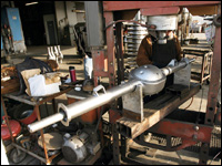 |
| Back at Currie, which is fortuitously only a few miles from
CPP, the axle casing was placed in this straightening jig once the axle
pads had been fully welded. A length of round stock was passed through the
bearing carriers in a third member used for just this purpose. A solid steel
tool that takes the place of an outer axle bearing was slid onto the stock,
and the press was used to "adjust" the casing at the inner end
of the axle tubes until the bearing substitute was a perfect fit. |
|
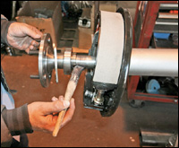 |
| Coming together, our axle also employs 11-inch drum brakes,
28-spline shafts, and a 3.55:1 gear ratio. This should be ideal for cruising,
especially with the Gearstar 200-4R overdrive trans we're using, and with
plenty of stopping power. While we're not going to make this a step-by-step
axle buildup, it doesn't hurt to pass on tips, such as greasing the shaft
before passing it through the seal. Our shafts had been drilled for a Chevy
5-on-4-3/4 stud pattern. |
|
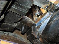 |
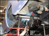
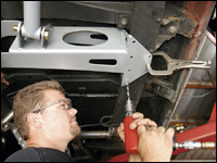
| As explained, I'd long ago C-notched the frame and installed
a couple of transverse thick-walled 2x1-inch crossmembers in anticipation
of fitting airbags. CPP fabbed a couple of top mounts with tabs to locate
the ShockWaves I'll now be using, as well as adding gusset plates down to
the chassis 'rails. Note also, progressive bumpstops are now in place in
the C-notches. |
|
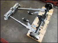 |
| While Currie welded, straightened, and assembled the axle,
CPP had sent out the crossmember, trailing arms, Panhard rod, and assorted
bracketry to be powdercoated. Note this kit uses the same trailing arms
offered in CPP's truck kits, which is why it features spring/airbag mounts
on the top surface. Production kits for cars with stock floorpans (in other
words, not C-notched!) may well make use of these, though ours employs brackets
located on the axle U-bolts to mount the ShockWaves. |
|
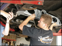 |
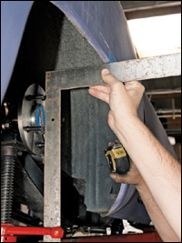
| CPP's Craig Chaffers held the new crossmember while it was
clamped in position. Note the large holes through which the exhaust system
will eventually pass, keeping everything up above the lower edge of the
chassis 'rails, which is important on a low car. |
|
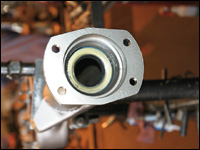 |
| The end seals were installed once the housing was deemed straight.
Not only does our axle have 3-inch tubes, but it also features Torino large-bearing
housing ends. |
|
|
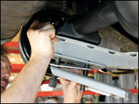
| With the crossmember clamped to the 'rails, the trailing arms
were hung from it before being attached to the axle using U-bolts, in the
same way Chevy truck axles are mounted. A bracket for the Panhard rod and
another that serves as the lower mount for the ShockWaves were also located
before the U-bolt was passed through all three components. |
|
 |
| On the other side, spacer plates were added above and below
the trailing arm to ensure the lower ShockWave mounts were the same height
on both sides of the car. |
|
 |
| With the U-bolts tightened and the trailing arms bolted to
the crossmember, diagonal measurements were taken to ensure the assembly
was square in the chassis before any mounting holes were drilled. |
|
 |
| With everything square to within 1/16-inch, Craig started
drilling the 3/8-inch mounting holes for the crossmember. If your stock
fuel line is still attached to the chassis, take care here not to drill
through it. The crossmember will bolt in place with all stock fuel and brake
lines still in position. |
|
 |
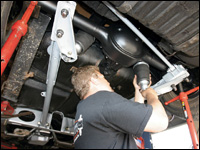
| The Panhard rod bracket was next clamped in position on the
driver-side chassis 'rail and mounting holes drilled. Note it clears the
stock fuel tank and fuel line. |
|
 |
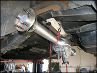
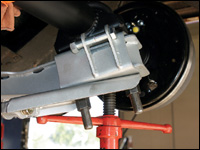
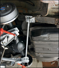
| The ShockWaves were the last components to go in. We opted
for the 9000-series versions with a 5-inch stroke, as their collapsed length
of 11.56 inches was perfect for our application. The offset pumpkin makes
their top mounts look very close together in this view, and indeed I may
look into fitting an antiroll bar at a later date, if body roll proves to
be an issue. |
|
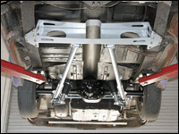 |
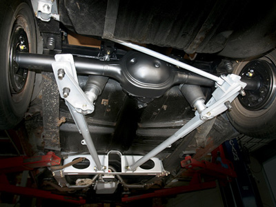
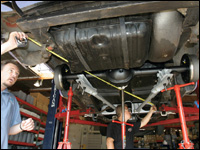
| Here's the complete assembly viewed from the front. I had
already replaced the driveshaft tunnel with a higher one that cleared the
closed driveline at full drop, yet the driveshaft is going to hit the tunnel
(the yoke hits on full drop) with the 8-inch axle, so the progressive bumpstops
in the C-notches should prevent this. |
|
 |
| I'm pleased with the stance on full drop, especially since
I never wanted it to "lay frame." This should provide a nice,
low ride height when raised a couple of inches. |
|
|