Power Steering Fluid
Most power steering unit suppliers will recommend the use of fluid that
the vehicle manufacturer recommends. What
do you do on a specialty vehicle with a GM pump and a Ford rack? Classic
Performance Products recommends the purchase of power steering fluid supplied
by a high quality oil company. The label will state if it is compatible
with Ford/ GM/Chrysler, etc. Most systems require 2-3 quarts of fluid.
New vs Used vs Rebuilt
Purchasing used is gambling, especially when you don't know the history
of the source vehicle. When you connect a power steering pump to a rack
or gear, you are instantly contaminating one with the other. The fluid can
flow 8 to 10 quarts a minute and at that volume, it doesn't take long for
the contaminated fluid from one unit to infect the other. So, now your choices
are new or rebuilt. In many cases, new is no longer available and in some
case a new unit may never have been tested. The advantage of a Classic Performance
Products unit is that most of the older units are still available and CPP
test every unit that we sell. CPP can also custom build a unit to your requirement.
Noise Through the Column
Unless a vibration dampener or isolator is used
in the column shafting, you can expect to hear a hissing noise traveling
up through the column. Sometimes this can be quite irritating, so we recommend
you plan ahead an incorporate one into your shafting/U-joint measurements.
Speaking of the Column
As a reminder, when designing your column make
certain the input shaft or the rack or gear is taking no forces except rotational.
Any downward, upward or side forces will cause erratic steering and premature
failure of the unit.
Fasteners
All bolt and nut fasteners are important attaching parts in that they can
affect the performance of vital components. If replacement of these fasteners
becomes necessary, style, type, quality and grade MUST be equivalent to
OEM. DO NOT use a lesser substitute. Torque values must be maintained during
assembly to assure proper retention of vital
components.
Pressure Reduction
It is commonly thought that a GM/Saginaw style pump will not mate well with
a Ford rack. In fact Ford uses Saginaw pumps on some rack & pinion equipped
vehicles. Most all passenger car steering systems utilize pressure between
1000 and 1200 PSI. Classic Performance Products recommends the following
procedures when building your specialty vehicle:
1. Initially, utilize stock pressures on the power steering
pump.
2 Caster setting should be between 4-6 degrees positive.
3. After a few test drives, reduce pump pressure ONLY when the vehicle has
too much power steering assist at a parallel park situation.
Lowering pump pressure reduces assist at all speeds and
power steering is needed most at low speeds. The high positive caster setting
will tend to tone down the effects of power steering at high speeds and
will give the vehicle good returnability from a turn. A pressure reduction
kit can be purchased from Classic Performance Products that will reduce
pressure on all FM style pumps.
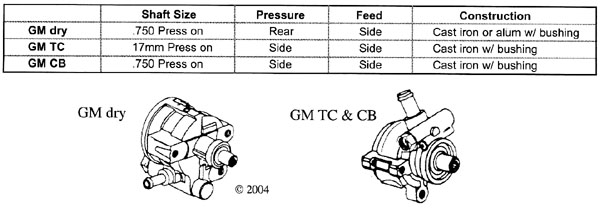
Remote Reservoir Set-ups
When using the small GM/Saginaw pump with a remote reservoir, we recommend
locating the reservoir as close to directly overhead the pump as possible.
An example of too far away would be locating the reservoir at the firewall
when the pump is near the front of the motor. The feed hose connecting the
two should be a minimum of 5/8 hose firm wall and if an AN style fitting
is to be used on the pump intake it must be a #10 and no less. These pumps
can mount in any position with the shaft facing forward. There are three
styles of this pump.
Getting It Up
Building a street rod or other specialty vehicle requires a different set-up
procedure than just replacing a worn out unit. Power steering systems are
self bleeding, but we must help them a little along the way. It is preferred
that the power steering system be the last engine. After everything is working
fine and all your adjustments are complete, now is the time to hook up the
power steering pump belt.
V-Belt System
1. Fill the steering system with your high quality fluid and let it set
undisturbed for a few minutes while you recheck your work. Leave the reservoir
cap off. Use this time to wipe the components off in preparation for leak
check and visually inspect the hose routing, belt alignment and attaching
hardware.
2. After your inspection, raise the front wheels off the
found and support the vehicle. Without starting the engine slowly begin
to cycle the steering wheel. The key here is "slowly"; about 1
revolution per 8-10 seconds. Continue to top off the fluid level at the
reservoir. When the level remains steady, inspect for leaks and start the
engine.
3. Check the fluid level and inspect for leaks. Some vane
type pumps require 1000 RPM or more to take the fluid down. Slowly cycle
the steering wheel in both directions, lightly contacting the wheel stops.
Continue to check the fluid level and add if necessary. If the pump begins
to get noisy, turn the engine off and let the system set for 15 minutes.
Air in the system will cause the pump to growl and the fluid level may rise
when the engine is turned off.
4. Repeat the above steps until the system is operating
normally. If air is still a problem after several rest periods, it may be
that air is entering the system faster than it can be expelled at the reservoir
fill. Look for leaks. Even the smallest of fluid leaks can be a source of
massive amounts of air entering the system.
5. Always test drive the vehicle, making sure it is safe.
Serpentine Systems
Obviously, the serpentine system does not allow for engine startup prior
to power steering startup. Therefore, follow all of the above steps and
take special precaution on step #2.
Six Easy Steps to Ordering a Steering System
1. Determine whether you will need a two or three U-joint
system. This is dictated by the angle, we recommend a 15 degree angle for
the optimum system, however up to 30 degrees is acceptable. If using a three
U-joint system, a support bearing is necessary. The center U-joint will
either be 3/4"00 x 3/4"00 or 3/4"00-36 x 3/4"00-36,
depending on whether you are using splined or DD shafts.
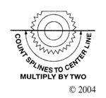
2. Use the Application Guide to select the rack and pinion
or box spline size you require. If the chart does not list your application,
just measure the diameter of the shaft and count the number of splines.
If there is a flat, count half the splines and double that.
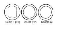
3. Measure your column (two rounds, two flats), measure
the round-it will either be 1"DD or 3/4" DD. If splined, measure
the diameter and count the splines i.e. 1"-48 or 3/4"-36.
4. To determine shaft length on a two U-joint system, measure
the distance between the rack and pinion or box shaft and the column, then
subtract 3.25 inches.
5. If using a three-joint system, we recommend using dowel
rods to mock up the system. Just measure the length of the dowel rod and
this will be the length of your shaft. Of course, you will need to order
U-joints prior to shafts.
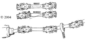
Important Notes:
Phasing - Keep the forks of the yokes closest to each other In line and
center of the shaft to avoid binding.
Set screws are supplied on all Splined and "Double
0" U-joints. However, it is necessary to indent (by drilling) the shaft
to properly secure the set-screw mechanism. Loc-Tite should also be used.
The shaft should be flush with the ends of the U-joint
yoke - too short could sacrifice strength and too long will cause the shaft
to interfere with the operation of the U-joint. |
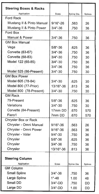 |
| To determine the spline size of a component (rack and pinion,
steering column and steering box), measure the outside diameter and count
the number of splines. If there is a flat spot on the shaft and some of
the splines are missing, count halfway around where there are splines and
double that number. We need to know how many teeth are in a theroretical
full circle. |
 |
Available U-joint Combinations are:
A) Smooth Bore on both ends
B) Smooth Bore and Spline or Double D
C) Spline and/or: Double D on each end. |
 |
|
Common Fitting Sizes
Because there is no clear rule of thumb, we list
below some of the more common power steering fitting sizes. There are many
others not listed and if you have questions about them, please call.
|
Pressure |
Return |
| GM Metric Pump |
16mm (M16-1.5) O-ring |
Push / Clamp |
| GM SAE |
3/8 tube size (5/8-18 inv. fl.) |
Push/Clamp |
| GM R&P |
18mm (M18-1.5) O-ring |
16mm (M16-1.5) O-ring |
| GM Metric Gear |
18mm (M18-1.5) O-ring |
16mm (M16-1.5) O-ring |
| GM SAE Gear |
7/16 tube size (11/16-18 inv. fI.) |
3/8 tube size (5/8-18 inv. fl.) |
| Ford Must II R&P 1974 thru 7-5-77 |
5/16 tube size (1/2-20 inv. fI.) |
3/8 tube size (5/8-18 inv. fl.) |
| Ford Must II R&P 7-6-77 thru 1978 |
5/16 tube size (1/2-20 iny. fI.) |
3/8 tube size (5/8-18) O-ring |
| Ford T -Bird thru 1988 |
5/16 tube size (9/16-18 inv. fl.) |
3/8 tube size (5/8-18) O-ring |
Although we encourage the CPPcustomer to use inverted flare
fittings, there are other methods of sealing off hoses. In any case, avoid
the use of pipe or thread dope or Teflon tape. These products can get into
the hydraulic system and do substantial damage.
Torque settings:
Inverted flare fittings should be torqued to 25-24
foot pounds
A-ring beaded hoses should be torqued to 20 foot pounds
Teflon ringed hoses should be torqued to 14-20 foot pounds
Other common torque settings:
Mustang R&P to cross member: 80-100 foot pounds
Ford R&P to cross member: 41-54 foot pounds
Gear to frame mounting bolts: 60-65 foot pounds
Pitman arm to sector retaing nut: 235-250 foot pounds
Pump keyway style pulley: 60 foot pounds |
 |
Rack & Pinion Pump Diagram:
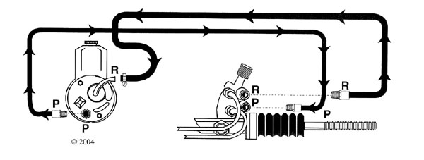
|