| Installation Notes: |
| 1. |
Note the original axle centerline and remove all of the original
rear suspension parts including: springs, rear axle, shocks, brake-line
and all hardware. |
| 2. |
Out off the original spring hangers and grind excess flush
with frame. |
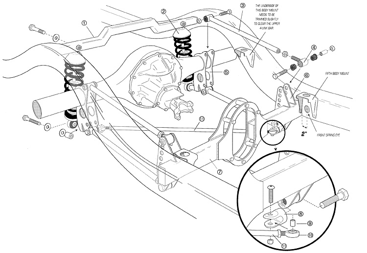
| 3. |
Measure the distance between the inside frame rails, just
directly behind the fifth body mount (see illustration). Cut the 4-link
crossmember (part No. 7) to this dimension. If you are centering the differential
housing on the middle of the axle, then the pinion yoke will be off-center.
Make sure that the driveshaft is centered on the driveshaft loop. This can
be done by offsetting the driveshaft loop (1" to the passenger side
for 9" Ford housing). |
| 4. |
Locate the 4-link crossmember on the inside of the frame,
directly behind the fifth body mounts (see illustration). The front part
of the crossmember is about 2" behind the front spring eye. Make sure
that the bigger part of the drive shaft loop is on top and tack weld in
place. Also, make sure that the bottom of crossmember is flush with the
bottom of frame. Sometimes, the parking brake cable bracket may need to
be trimmed off in order to do this. |
| 5. |
Double check the location of crossmember (diagonal and squareness)
and final weld crossmember onto frame side. |
| 6. |
Install frame side 4-link brackets (Part No. 6) on the 4-link
crossmember, with more of the adjustment holes on the top side. Center of
brackets should be 28" apart. Tack weld. double check measurement (make
sure it is centered on the crossmember) |
| 7. |
Tack weld the coil-over crossmember (part No. 1) with the
front part of it located 2-1/8" behind the axle centerline. |
| 8. |
Tack weld the axle brackets (part No. 5) on the rear axle
with the centers at 28". Position brackets so that the pinion angle
is down 1.5 degrees when the rear of axle brackets are vertically straight. |
| 9. |
Mock assemble adjusters (part No. 4) into the 4-link bars
(part No. 3) and install rear axle into frame using 4-link. Install track
bar (part No. 11). Double check all measurements, diagonal and squareness
including wheelbase (115"). |
| 10. |
Disassemble and final weld everything. |
| 11. |
Reassemble the 4-bars with the adjusters toward the front
and tighten all bolts and nuts. Double check pinion angle and wheelbase. |
| 12. |
Install track bar and adjust so axle is centered (side-side)
within the frame and tighten all nuts and bolts. |
| 13. |
Adjust coil-over shocks (part No. 2) so that the center of
the top mounting bolt is about 13" to the center of the bottom mounting
bolt. |