| Installation Notes: |
The installation of Total Cost Involved's Mustang independent
front suspension unit is really very simple because Total Cost Involved
has engineered all the correct angles and geometries onto the crossmember
itself. All that is required are a few careful measurements to locate the
crossmember and the spring mounts correctly on your chassis before welding
them into position. Minor trimmings may be necessary for some variations
in the frame.
We recommend that all of the welding should be done by
a qualified welder using the proper techniques. We also recommend that the
initial and subsequent wheel alignment should be done by a qualified alignment
shop. |
| 1. |
PREPARING THE FRAME |
|
· Remove all of the old suspension and steering components
and mark the axle centerline on frame. |
|
· Do not remove any crossmember except a slight trimming
on the rear side of front crossmember on the '55-'59 Chevy pickup is necessary
to clear the rack & pinion. |
|
· Clean the frame of any dirt/rust and weld on the
supplied boxing plates. |
|
· Finish grind all welds. |
| 2. |
INSTALLING THE CROSSMEMBER |
|
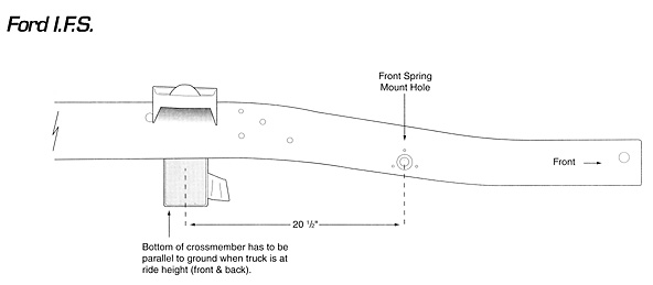
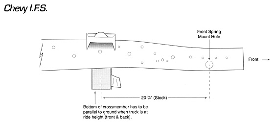
· Fit the crossmember squarely an the top of the rails
with the rack & pinion mount facing to the front of car. The centerline
of the cross member should be inline with the axle centerline (figure #4). |
|
· The bottom of the crossmember should be parallel
to the ground with the frame sitting at ride height (front and rear). |
|
· Inside measurement between frame rails should be
29". If there is any gap, this can be filled with by adding shim plates
equally on both sides. |
|
· Basic location of axle centerline is given in figure
#3, check your wheel base to determine your particular application. |
|
· On the '53 - '56 Ford pickup, the axle centerline
may need to move forward 1-1/4" to center the wheel inside the fenders.
Please check your own application. |
|
· Tack weld lower crossmember. |
|
· If you are using the Total Cost Involved's tubular
lower control arms |
|
A. Drill the lower control
arm holes in the crossmember to 5/8". |
|
B. Position the longer
steel spacer on the rear side of the crossmember (using the lower control
arm mounting bolts through the crossmember as an alignment guide) with the
reinforcing gusset mounted horizontally toward the engine. |
|
C. Tack weld the spacer
and gusset together and to the crossmember. |
|
· Double check all measurements including wheel base
dimension and diagonally for squareness. |
|
· Final weld the crossmember to frame on all sides. |
| 3. |
INSTALLING SPRING MOUNTS |
|
· Position the spring mounts on the top, outside edges
of the frame rails, with its centers directly over the center of the lower
crossmember and axle centerline (figure #4). |
|
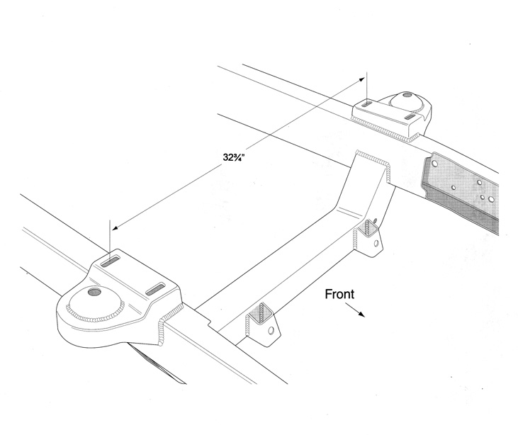
· The distance between the middle of upper control
arm adjusting slots should be around 32-3/4". Adjust the hats in or
out of the frame by trimming or adding shim where the hat meets the sides
of the frame. |
|
· To determine the left and right sides, the spring
mounts should sit slightly lower in the rear to maintain the proper antidive
geometry. |
|
· Tack both spring mounts in place, double check your
measurements (also diagonally for squareness). |
|
· Mock up the upper control arm, lower control arm
and the spindles, raise or lower the spindles until the lower control arm
is horizontal to the ground and check the wheel camber. Make sure there
is enough adjustment to set the spindle at 0º camber. |
|
· Final weld spring mounts to the frame on both sides. |
| 4. |
COMPONENTS ASSEMBLY |
|
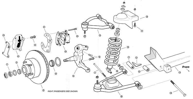
· Install the lower control arms and strut rods, if
applicable, into the crossmember. Tubular control arms should be mounted
with the shock bolts toward the rear side. |
|
· Install the upper control arms, with the serrated
side of the cross shaft facing down, using the special button head bolt,
FORD #385713-S-101. |
|
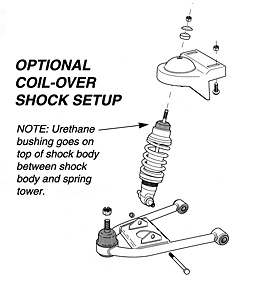
· Install the coil springs and spindles, with the steering
arms toward the front side. |
|
· Install brake rotors, calipers and brackets, rack
& pinion steering unit, and shock absorbers. |
| 5. |
SUSPENSION ALIGNMENT |
|
· Set ride height so the lower control arms are horizontal
to the ground and align the wheel with the following specifications: |
|
Camber at 0º Caster
at 1º Toe in at 1/16" |