Safely support vehicle at the finished ride height with the
desired front to rear rake at both the front and rear. Remove the existing
front suspension. Do not remove the front spring shackle mounts riveted
in the frame as they are used for a measuring location. You will also need
to modify the part of the frame rail that is turned up for the old steering
box mount so that portion is flat.
Boxing the front frame section is next using the supplied boxing plates.
The boxing plates should fit up against the radiator crossmember. You can
grind the inside edges of the frame rails flat so that the plates lay flat
against them, but you need to make sure you do not grind off too much and
make the rails too thin. The boxing plates can set on the lower flanges
of the rails in the front, but most of the flanges will eventually be trimmed
away for the rack C-notch and crossmember clearance. Fit the boxing Plates
to the frame rails, weld and grind smooth. |
|
|
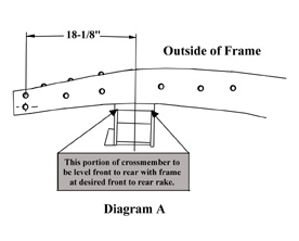 |
Measure back from the center of the front spring shackle hole
in the frame and make a vertical line as shown in Diagram A.
This will be the cantor of the crossmember and the spindle centerline. Slip
the crossmember up into the frame and center it on the centerline mark.
If it doesn't fit in the frame, grind the sides of the crossmember uprights
until you can got it into position. Make sure that the crossmember is all
the way up into the frame and seated against the underside of the frame
rail. Be sure top of flat portion of crossmember is mounted level front
to rear, with frame at desired front to rear rake. This is important for
proper alignment. You can tack the crossmember into place for now. |
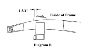
| Now you can install the shock towers. The shock towers sit
on top of the frame rails located 1 3/4" forward of the front of the
crossmember. See Diagram B. The taller part of the shock tower
is the front part and should be positioned toward the front of the vehicle.
Fit the shock towers fully against the side of the frame rails. You can
also grind them to fit against the tops of the rails. Now tack weld the
shock towers in place. |
 |
 |
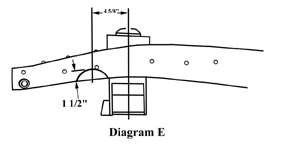
The C-notch for the rack is the last part to be done. Measure
forward 4 5/8" from the centerline and up 1 ½" and make
a mark. Now draw a 2 1/8" radius using your mark as the top of the
radius. See Diagram E. Cut out the material inside the radius
to form the notch leaving 1/8" of material inside the notch for precise
fitting. Try the fit of the C-notch plate. Finish grind the notch for a
good fit and correct location of the C-notch plate. Tack weld the plate
in place. Remove the rack after C- notching both sides of the frame. |
|
|
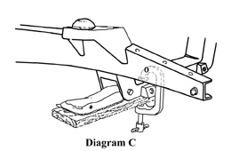
| We do not recommend using strut rods. Tubular control arms
distribute brake load much better. If you choose to use strut rods - use
the following instructions. The lower control arms and strut rods can be
used for locating the strut rod plates and gussets. Using a 2x4 and a C-clamp,
install the control arms as shown in Diagram C. Install the
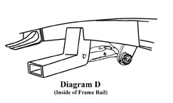
strut rods onto the control arms. Assemble onto the strut rod ends the large
rubber bushings, including the cupped washers, and strut rod plates. Align
the tops of the plates with the underside of the frame rails, then fully
tighten the nuts on the strut rods to their fully seated position. See
Diagram D. The Pinto and Mustang strut rods are different lengths.
We recommend the Pinto strut rods, as they are shorter and will position
the strut rod plates more closely to the underside of the frame rails. The
Mustang strut rods can be used, however, by heating the rod at the bend
at the ball joint end and bending out enough to align the strut plates to
the bottom of the frame. The strut rods will act as alignment fixtures while
you tack weld the plates in place, then tack weld the gussets in place also.
See Diagram E. Now you can remove the strut rods and control arms. |
|
|
 |
 |
|
|
| Now you are finished with the crossmember assembly. Install
the rest of the front end. When the rest of the car is complete you can
use the following information to align your front suspension: |
|
|
| With vehicle weight and at ride height specifications are: |
| Camber: 0 degrees Caster: 1 - 1-1/2 degree positive, Toe in
1/16" for radial tires or 1/8" for bias ply tires. |
|
|
| Please note - It may take 100 or more miles of driving for
the springs to fully settle to ride height. They may settle 3/4" -
1" |