| Classic Performance Products |
| 1963-72 Chevy Truck Tubular Suspension Install
Part Three - Disco Brakin' |
| By Bob Ryder |
|
|
Brakes are one of the major concerns of early-model trucks.
When restoring a truck today, an upgraded brake system should be mandatory,
and with today’s aftermarket disc brake conversions, you’d be
foolish not to make the investment when upgrading your brakes. We have been
working with the team at Classic Performance Products in Anaheim, California,
while they upgrade a ’67 Chevrolet ½-ton pickup frame with CPP
suspension components on all four corners, and in this last installment
we’ll swap the front and rear brakes.
A quick recap to show the build from beginning to end |
Totally
Tubular Part I
We covered the installation of CPP’s Big Tube rear
suspension featuring 2-inch-diameter trailing arms with urethane bushings.
The track bar (Panhard bar) eliminates any lateral movement of the rearend
housing. A pair of shorter progressive coil springs and gas-filled shock
absorbers were installed. A flat frame cross member replaced the factory
crossmemeber to allow more ground clearance following the lowered stance.
The cross member also has oversize 3 x 5 inch oval exhaust pipe holes, allowing
the exhaust to be tucked up inside the framerails. The CPP rear suspension
lowering kit allows a 6-inch drop. |
Totally
Tubular Part II
The '67's nose was dropped by installing CPP's tubular
1-3/4 inch upper and lower control arms. The lower A-arms lower spring pocket
features a one-piece stamped steel spring pocket that is completely flush
with the bottom edge of the lower A-arm for maximum ground clearance. A
pair of zinc-coated control arm cross-shafts with self-locking hardware
maintains continuous alignment. New CPP tie rod ends and adjusting sleeves
were installed, along with new pitman and idler arms and a power steering
box. Body roll was eliminated with a thicker diameter sway bar. To achieve
the 5-inch lowered stance up front, a pair of CPP 2-inch drop spindles and
3-inch- shorter progressive coil springs were installed. Up front, we also
installed a pair of Totally Tubular engine mounts and a Totally Tubular
transmission crossmember. |
Totally Tubular Part III
In Part III, we will be following Jeft Wise and Danny Nix
as they install CPP's four-wheel disc brake kit. The large 12-inch brake
rotors are cross-drilled, chamfered, and slotted before they are zinc-plated.
Cross-drilling increases the rotors' ability to cool down between stops
by exerting heated gases that build up inside the rotors' metallurgic molecule
structure due to friction during stopping. The rotors' cross-drilled holes
are chamfered to eliminate cracking that can occur when rotors develop stress
concentrations during the drilling process. Slotted rotors will reduce brake
fade during stopping and maintain a clean brake rotor surface as the brake
pads sweep the rotors' surface. A complete set of inner and outer wheel
bearings, seals, castle nuts, cotter pins, and spindle dust caps are included
in the kit.
The CPP front caliper pistons are among the largest available
with a 2 15/l6-inch bore and a piston area of 6.8 square inches. A pair
of zinc-plated backing plates helps deflect debris from interfering with
the brake rotor and caliper. The rear calipers are big and incorporate an
integral parking brake. Rear calipers feature a 2-inch bore and have a piston
area of 3.1 square inches. The rear brake lines are all pre-bent for exact
fitment connecting with flare fittings to either rubber or stainless braided
Teflon brake hoses with banjo fittings connecting to the calipers.
Knowing the crew at CPP are early risers, I arrived
with pre-dawn fresh doughnuts and coffee. After unpacking my camera bag
and inserting an empty flash card, I was ready for action. |
 |
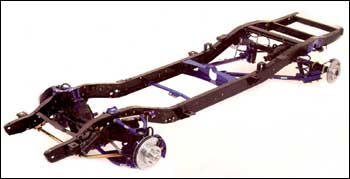
| 1..This front view of the '67 Chevy pickup frame with CPP
front suspension components includes CPP upper and lower control arms with
ball joints and urethane bushings, 2-inch drop spindles, 3-inch shorter
coil springs, gas-filled shock absorbers, L&R tie rod ends, tie rod
adjuster sleeves, power steering box, pitman arms, idler arm, front sway
bar, sway bar, and end links. |
|
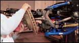 |
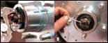
| 2..Jell Wise removed the front brake rotor that had accumulated
decades of crust and rust. |
|
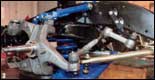 |
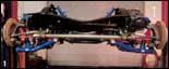
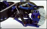
| 3..Here we can observe the immaculate CPP upgraded front suspension
components (covered in our earlier tech articles "Totally Tubular Parts
I and II"). |
|
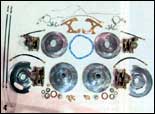 |
| 4..Here are the CPP front and rear disc brake conversion kits
for '62- 87 1/2- ton GM trucks. |
|
 |
| 5..A zinc-coated backing plate was then balled and secured
to the front spindle. |
|
|
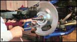
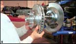
| 6-7..Jeff then proceeded to align a new CPP 12-inch cross-drilled,
vented, and zinc-coated rotor onto the CPP 2-inch dropped spindle. |
|
 |
| 8-9..After the rotor was aligned onto the spindle, a castle
nut was snugged up using a pair of slip-jaw pliers, then secured with a
cotter pin. |
|
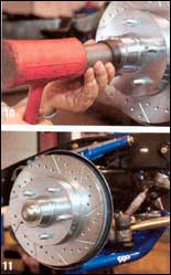 |
| 10-11..A special dust cap installation tool was used to evenly
distribute the impact while installing the dust cap onto the spindle. |
|
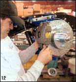 |
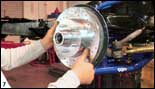
| 12..The single-piston front brake caliper was then aligned
and mounted to the spindle. |
|
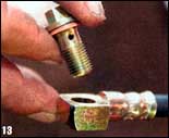 |
| 13..A banjo boll was used to thread the banjo fittings on
the rubber brake hoses. |
|
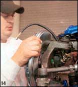 |
| 14..After the banjo bolt was installed into the brake hose's
banjo hose fitting, it was then threaded and secured into the brake caliper's
brake line fitting. |
|
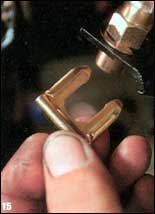 |
| 15..A C-clip secured the front brake hose to the mounting
bracket located on the framerail. |
|
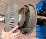 |
| 16..Moving to the rearend housing, Jeff removed the brake
drum, exposing the rear brake shoes and backing plate assembly. |
|
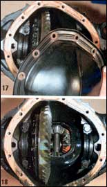 |
| 17-18..The rear differential cover must be removed to gain
access to the rear axles, which need to be removed from the rearend axle
housing. This allows the rear brake shoe assembly to be removed. |
|
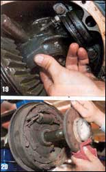 |
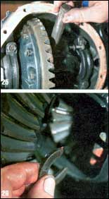
| 19-20..After loosening the center-locking pin bolts, the locking
pin was pushed out halfway. The rear axles were then pushed inboard to relieve
the tension on the C-clip, which was then removed. Alter the C-clip was
removed, the axles were pulled from the rear-axle housing. |
|
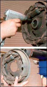 |
| 21-22..The rear brake shoe assembly was unbolted from the
rear-axle housing flange and removed. |
|
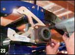 |
| 23..After the rear brake shoe assembly was removed, the CPP
rear disc brake caliper mounting bracket was secured to the rear- axle housing
flange. |
|
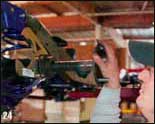 |
| 24..After the CPP rear disc brake caliper mounting bracket
was secured, the rear axles could be reinstalled. |
|
 |
| 25-26..Continuing with the build, the rear axles were inserted
into the axle housing. After aligning and reinserting the center locking
pin, the C-clips were reinserted. |
|
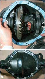 |
| 27-28..To eliminate any differentiailluid leaking, a new gasket
(supplied in kit) was sandwiched between the differential and the cover.
The differential cover was aligned and the 12 bolts were secured. |
|
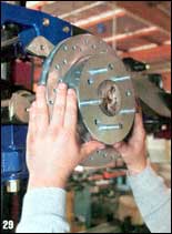 |
| 29..The rear disc brake's 12-inch, cross-drilled, slotted,
and zinc-coated rotor was aligned over the rear axle. |
|
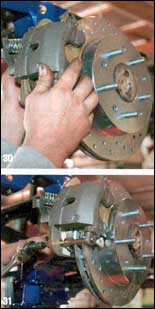 |
| 30-31..Next up, the CPP rear disc brake caliper pads were
spread and then slipped over the rear brake rotor. After the rear brake
caliper bolts were aligned, the long caliper bolts were inserted and tightened
down. |
|
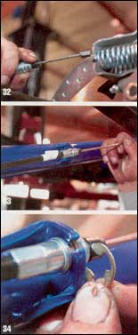 |
| 32-33-34..CPP rear brake calipers feature an internal E-brake.
The E-brake cable was inserted through the spring and secured. The other
end was secured at the sheath fitting with a C-clamp. |
|
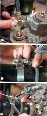 |
| 35-36-37..Securing the hose to the caliper, a banjo fitting
was threaded into the rear brake caliper. A rear-brake hard line clamp wraps
around the rearend housing axle tube to secure the rubber brake line and
hard-line junction. |
|
 |
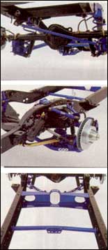 |
| 38..An overall inboard view of the completed rear disc brake
assembly displays the high-quality CPP components. |
|
|
| Go
To Part One Go
To Part Two |
|