 |
| Classic Performance Products |
| Tri-Five Straight Axle Clip |
| By Mike Harrington |
|
|
|
Here at Super Chevy magazine we have received numerous
e-mails from readers asking how to build a straight-axle Tri-Five. It seems
that over the past decade or so, the nostalgic gasser look of the '60s has
returned with a vengeance.
We won't bother going into the history of gassers in this
article. Suffice it to say the gasser look and stance was all about weight
transfer at the track. We put out the call for anyone doing a straight-axle
install, and a year or so later found ourselves heading up to Clearfield,
Utah.
The guys at Salt City Speed Shop (SCSS) answered the call
and let us stand over their shoulders as we documented them installing a
Jim Meyer Racing straight-axle conversion kit. |
The crew at SCSS was in the middle of setting up a new shop
location, so we moved the installation of the front clip to a more familiar
setting-the family home garage. To tell you the truth, during the course
of the install we kept expecting things not to fit quite right or run into
some sort of problem. It never happened. On several occasions, SCSS's Kris
and Larry Elmer commented on how well-engineered the Jim Meyer clip was.
The '55 Chevy rolled into the shop, and five days later it rolled out of
the shop, complete and ready. Due to the length of this install article
we are going to jump right into the specifics. What you see is what you
get. The rear-steer leaf-spring suspension includes everything you'll need
to install it into a stock 115-inch wheelbase Tri-Five frame. |
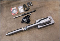
The straight axle assembly is complete with tube axle (any
width), leaf springs (rated at 3,500 pounds for the pair) with front shackles
and rear-frame brackets, shocks with frame-mount brackets, new Super Bell
early Ford spindles with bolt-on Super Bell 2-inch dropped steering arms,
new cross-steer Vega steering box with 2-inch dropped Pitman arm and cross-steer
drag link and tie-rod. It features Wilwood 4-piston calipers with 10 3/4-inch
rotors with a 5-on-4 3/4 wheel-bolt pattern to fit inside nostalgic 15-inch
wheels. Included are box tube grafting sections to install the new suspension
to the stock chassis that will be cut at the first body mount, just in front
of the firewall. Also in this subframe kit are steering linkage hook-up
kits or new ididit steering columns and disc/drum brake kits that plumb
into your existing brake system. |
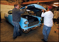 |
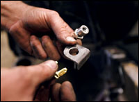
| The first obvious steps were to start dismantling the entire
front end of the vehicle. During the dismantling process, the guys at Salt
City Speed Shop tagged and bagged every nut, bolt, and wire. It helped prevent
migraine headaches during the reassembly. |
|
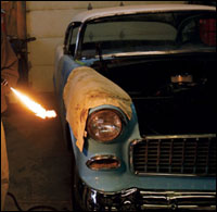 |
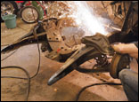
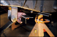
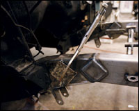
| Larry Elmer, Kris's father, sparked up the blowtorch to cut
loose some rusted and stubborn bumper bracket bolts. Penetrating oil did
nothing to release the fused bolts, so this was a last-resort measure. |
|
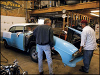 |
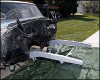
| Progress is being made. The front sheetmetal was removed and
set off to the side. Now it was easier to look at what might be hiding under
the skin of this vehicle. |
|
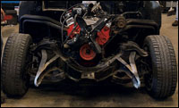 |
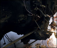
| Kris Elmer was amused after taking a close look at the Chevy
frame. It was in bad shape. The frame was cracked in two different places,
and the driver's side spindle was bent, causing some serious negative caster
issues. The passenger's side of the frame was also bent and had some horrible
negative camber issues. In short, it was sort of like a pretzel frame. If
ever there was a candidate for a straight- axle install, this former wheel-hopping
'55 was a perfect choice. There was no saving this front end. |
|
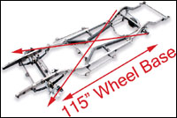 |
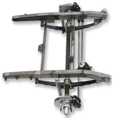
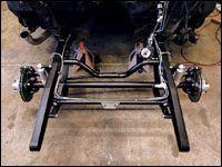
| This photo is actually of a complete Jim Meyer straight-axle
chassis. We couldn't find photos of a bone stock frame, so we used this
one to illustrate the measurements taken. SCSS didn't trust any of the measurements
from the misaligned frame, so the guys chose a different method. Typically
one would establish the wheel alignment and position by the wheelbase of
the vehicle in question. In this case, the '55 Chevy had a 115-inch wheelbase.
Measuring diagonally from corner to corner in the center of each hub is
the typical method for determining where the new wheels and axle will sit. |
|
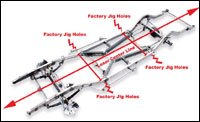 |
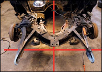
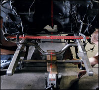
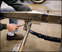
| Here's how they did it. First they located the factory jig
holes on the frame in the front and the back. A measurement using the jig
holes as a reference point was taken from left to right in the back, and
from left to right in front. Then the center of these jig hole measurements
was established. Luck was on our side-when the laser sight was used, the
centers lined up perfectly. We now knew the rest of the frame, minus the
front, was accurate and in good shape as far as alignment goes. We then
measured 115 inches from the center of the hub on the rear axle to the center
of the front hub on both sides of the vehicle in order to determine the
factory wheel position and centerline. That factory wheel position was where
we planned to install the new straight axle. We all like altered-wheelbase
cars, but not an accidental altered wheelbase through poor measuring. |
|
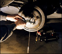 |
| Using a plumb bob and micrometer to check the hub centerline,
the SCSS crew made one more measurement, using the traditional diagonal
measurement style to double check themselves. |
|
 |
| After all the measurements were taken, checked, and re-checked,
a marker was used, and the horizontal and vertical lines were drawn on the
floor for future reference. Since the car was on jack stands and leveled,
there were no worries about where to place the new axle and wheels. |
|
 |
| Now the fun begins. Kris used a plasma cutter to snip the
front of the '55 off. This is the point of no return; if we weren't committed
in the beginning, we sure were now. |
|
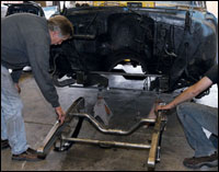 |
| When the front of the original frame was cut off, it was deliberately
cut too short. More metal can always be trimmed back to fit the new piece.
The new straight axle clip was placed under the frame and mocked up in order
to see how much more metal needs to be shaved off. |
|
 |
| After further cutting, this is the result. More was taken
off the bottom than the top, and this gave us some wiggle room for leveling
the clip. |
|
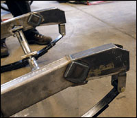 |
| The very ends of the new clip were also clearance-cut in order
to make it easier to fit into the channels in the old frame. |
|
 |
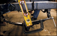
| Once again the same methodical process of measuring, using
a laser level and plumb bob are used in order to match the new frame to
those of the previous measurements. The frame and axle center were aligned
to the measurements and lines that were drawn on the pavements surface.
After the vehicle is built, the only wheel alignment that can be performed
is toe in or toe out. Prior to the finished product, all alignment has to
be built into the suspension. The reason for all the re-measuring is to
take into account all the tolerances of the new frame. The geometry of the
new parts needs to match the geometry of the old. Once all that is figured
out, it's full steam ahead. |
|
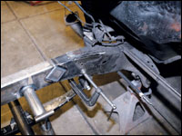 |
| Now the frame can be tacked into place and checked again if
need be. |
|
|
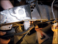
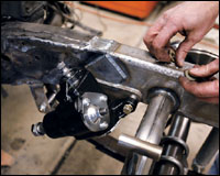
| In order to provide more support to the weld joint, a small
patch panel was fabricated by the shop and tacked into place just behind
the spring bracket. This added surface area for the weld will greatly increase
the frame strength. We later found out that these pieces were included in
the kit, but were somehow missed. |
|
 |
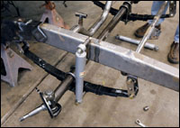
| Now that the entire front clip is welded into place, Kris
and Larry assembled and mocked up the rest of the components to see just
how everything would align. In this photo you can see what looks to be two
possible spring locations for height. However, the lower hole is the correct
size and location. The center hole is there for looks. |
|
 |
| The Super Bell axle and spindles were also temporarily assembled
and installed. Just like the springs, the axle also has two possible locations.
The axle can be set on top of or below the springs. Below the springs will
give the front end a higher ride height, while on top of the springs will
give it a lower altitude. Since the springs were installed higher, it was
decided to install the axle to bring the height down by a few inches. |
|
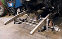 |
| Before any of the steering was assembled, here's where we're
at: First off, it was amazing to watch the methodical installation performed
by Kris and Larry Elmer. Every part in the Jim Meyer kit worked exactly
as it was supposed to work. During the install and assembly, Larry Elmer
kept remarking what a well-engineered set up Jim Meyer made. Back in the
day, Larry built a straight-axle '55 Chevy from scratch. He said our five-day
project took him two months back then. |
|
 |
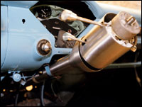
| While the Jim Meyer subframe comes complete with a Vega steering
box, we used one of Classic Performance Product's (CPP) units. We also got
the optional telescoping double D steering shaft, Borgeson U-joints and
ididit column from CPP, which had them on the shelf and readily available
for next-day delivery to our shop in Utah. You can also purchase the item
directly from Jim Meyer. |
|
 |
| No need to worry about drilling holes into the frame for the
Vega box. |
|
 |
| The ididit column from CPP went in like it came from the GM
factory back in 1955. |
|
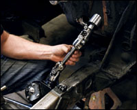 |
| Once the column was in, the double D shaft was trimmed down
and the Borgeson U-joints are installed on the shaft. It turns out we didn't
need to use the telescoping shaft. There just wasn't enough room. |
|
 |
| The one thing that didn't come in this kit was brackets for
the brake hose. Kris did a splendid job at fabbing up a set. |
|
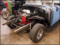 |
| Once everything was assembled, the engine was installed to
weigh down the suspension and check out the work that was performed. After
this, it was all taken apart again while more finishing touches were added.
Even the headers cleared the steering shaft. Score one for us-that's one
less headache to deal with. |
|
 |
| With the engine pulled out, it was time to set the caster
angle of the axle and spindles. We called the Jim Meyer tech line and asked
them what they recommended. We were told to set it between 5 and 8 degrees.
We set it at the maximum of 8 degrees. |
|
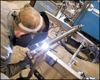 |
| With the caster set, the spring pads were TIG-welded into
place. As before, Kris would often switch sides while welding from left
to right in order to avoid heat buildup and warping the axle. |
|
 |
| The last bit of welding that was performed on the frame was
the addition of some reinforcement plates. It couldn't hurt to make sure
the frame was solid as the Rock of Gibraltar. |
|
 |
| The vehicle was rolled outside and the bare metal frame was
doused with self-etching primer, along with all the other parts. After the
primer dried, it was painted in a semi-gloss black. |
|
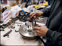 |
| While the paint was drying, Larry went ahead and assembled
the Wilwood brakes, packed the bearings, and made sure everything was ready
to go once the paint dried. The Wilwood disc brake system kit came with
everything we needed and went together with ease. These modern wonders are
going to help our '60s-look gasser safely stop like a much newer car. |
|
 |
| In the meantime, Kris spent a fair amount of time custom-fabricating
and installing all the new brake lines and bleeding the system. This is
the final shot before the engine goes back in permanently. What a fantastic-looking
project this turned out to be. |
|
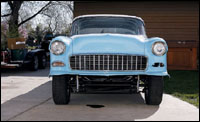 |
| All the sheetmetal is put back on and this is the view from
the front. |
|
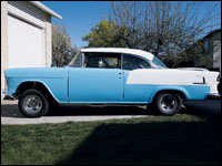 |
| Here's that all-important nostalgic '60s gasser stance that
looks oh, so cool! The wheel placement is perfect-all that careful measuring
paid off. |
|
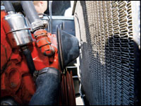 |
| After all the king's horse and all the king's men put the
Chevy together again, the only hiccup we ran into was the radiator position.
Notice how close it is to the pulley, leaving no room for the fan. That
problem was easily solved by moving the radiator to the other side of the
core support. Now it's time to uncork the headers and upset the neighbors. |
|
|