| Classic Performance Products |
| Engine Side Mounts and Cross Member Installation |
| Courtesy of Danchuk Manufacturing, Inc. |
|
| We would like to thank Danchuk Manufacturing, Inc. for providing
the following technical article and photos outlining the procedure for installing
side mounts and crossmember. The procedures are similar for any unit you
may be using and can be bolted in or welded. We are bolting them in as we
feel this is what most “do-it-yourselfers” would do. |
- You will need:
• Side Engine Conversion Brackets
• Side Engine Mounts
• Engine mounts and “L” brackets to support the rear crossmember
• Rear Crossmember
• Rear Transmission Mount
• Qty 4, 3/8” grade 5 bolts 1.25” long
• Qty 2, 3/8” grade 5 bolts 1” long
• Qty 4, 3/8” grade 5 bolts 5” long
- • Qty 8, 3/8” Lock Nuts
• Qty 16, 3/8” Flat washers
• Qty 2, 3/8” Lock washers
|
• Electric, Air or Cordless Drill
• 3/8” Drill Bit
• Level
• Tape Measure
• “C” Clamps
• Engine or Engine block
• Transmission or complete transmission case.
• Engine hoist or equivalent.
• Chain or engine strap.
• Mechanics Square or equivalent.
• Welder (if you plan to weld the mounts in place) |
In this article we will cover a couple of ways to find the
correct position for the side mount conversion brackets. In Method One we
will mock up an engine and transmission in the frame and measure for a correct
fit. In Method Two we will show you how to use the original mounts to find
the mounting spot. Both ways are acceptable and will yield satisfactory
results but Method Two can only be used when using conversion brackets putting
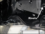
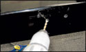
the engine in the stock location. 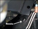 To give you a preliminary frame of reference,
the side mount conversion brackets will install on the frame just behind
the rivet on the frame where the frame starts to curve in at the front.
This rivet basically attaches the front area of the frame to the main side
rails. To give you a preliminary frame of reference,
the side mount conversion brackets will install on the frame just behind
the rivet on the frame where the frame starts to curve in at the front.
This rivet basically attaches the front area of the frame to the main side
rails. |
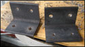
 The “L” brackets for the rear crossmember
will bolt or weld to the frame and the crossmember will sit on it and bolt
in place thus supporting the rear of the engine/transmission assembly. The “L” brackets for the rear crossmember
will bolt or weld to the frame and the crossmember will sit on it and bolt
in place thus supporting the rear of the engine/transmission assembly.
We will use an engine bolted to a transmission to get the
exact positioning; you can use just an engine block and transmission case
or one of the trick plastic engine blocks available if you have access to
one.  We do not recommend trying to simply measure
when installing these. Always mock up the engine and transmission in the
frame for best results. We do not recommend trying to simply measure
when installing these. Always mock up the engine and transmission in the
frame for best results. |
Method One
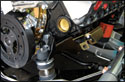
1. Install the engine side mounts on your engine or engine block and tighten. |
|
|
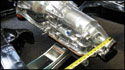
| 2. Install your rear transmission mount to the rear mounting
pad on the transmission. |
|
|
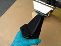
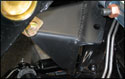
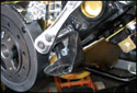
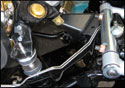
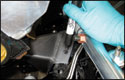
| 3. Hang the left and right side engine side mount conversion
brackets on the engine mounts. Do not tighten. |
|
|
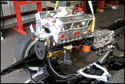
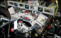
| 4. Connect your engine (or mock up engine) and trans to a
hoist and lift the assembly into the approximate position above the frame.
Getting someone to help position the side mounts, slowly lower the assembly
until the mounts are in position at the rivets. The “L” bracket
on the side mount conversion kit may not fit flush on the frame. This is
okay. The mounts shown mount the engine in the stock location and are for
a seamless frame. If you are using the 3/4” forward mounts for an HEI
or big block, the installation procedure will be the same as described here. |
|
|
| 5. Next you will place a level across the valve covers. Level
the engine assembly in the frame. (Be sure your frame is sitting on a level
surface before you try and level the engine in the chassis.) Pull the engine
assembly forward in the chassis until the side mounts hit the front rivets.
This will give you the preliminary position in the frame for the side mount
conversion brackets and you can now drop the engine so the brackets contact
the side rails and are holding the engine in place but the assembly is still
being supported by the hoist. |
|
|
| 6. Take a floor jack and place it under the rear tail shaft
of the transmission for support. Jack it up so the engine and trans is sitting
approximately where it needs to be. We will measure precisely in step 9. |
|
 |
| 7. With your tape measure, position the tail shaft so it is
centered between the frame rails. Now your front conversion brackets should
be in the correct position and you can lower your assembly further onto
the frame rails. Keep the assembly supported on the hoist until you are
completely done, however. We will not weld or drill holes for the side mount
conversion brackets at this time as we want to position and bolt in the
rear cross member before welding or bolting in the front mounts. |
|
|
Method Two
Method Two is very similar to Method One except you will install the original
mounts on the front of the motor and position the brackets where they fall
in lieu of “guesstimating” the position at the rivet.
Note: This method can only be used if you are installing
the kind of mounts that mount the engine in the stock position. Using this
method on the conversion brackets for HEI or big block will not position
the engine assembly in the proper position and allow clearance of the HEI
or big block valve covers at the firewall. HEI and big block brackets position
the engine/trans assembly 3/4” forward.
Once the original mounts are in place you will lower the engine assembly
into position on the original mounts and where the side conversion brackets
end up will be where you attach them to the frame. Leveling the motor and
centering the transmission between the frame rails is still necessary using
this method but it leaves no guesswork to the exact positioning of the engine
in the frame rails. As in Method One, we will not drill holes or weld the
mounts into place until the rear cross member is installed. Either Method
One or Two will yield satisfactory results but Method Two is easier and
requires less engineering. |
|
|
| Once you have the engine/trans assembly positioned in the
frame it is time to install the rear cross member. Once this is done the
position from front to back of the engine/trans assembly will be locked
in place. |
|
|
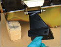
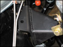
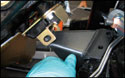
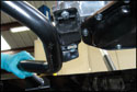
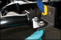
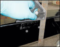
| 8. Position the rear cross member on the rear transmission
mount and bolt it in place on the rear transmission mount. |
|
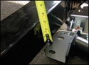 |
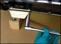
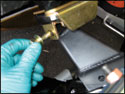
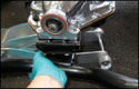
| 9. Adjust the height of the floor jack so the transmission
crossmember ends are about 1” or so above the bottom of the frame at
the highest point. The brackets will probably be on an angle. Take the “L”
brackets and clamp them to the ends of the crossmember. The transmission
crossmember will sit on the “L” bracket when installed. Each crossmember
will sit at a different height depending on your frame and engine/trans
assembly. Generally, your engine should sit on a 1-2 degree back slope.
Whichever crossmember you are using, position it accordingly. |
|
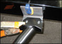 |
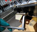
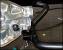
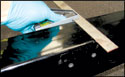
| 10. Once you have the brackets in place on the crossmember
bring them out and rest the back of them on the frame. Measure from the
top of the frame to the top of the “L” bracket and be sure the
measurement is the same for each side. This is to be sure the trans is level
in the frame. Also double check that the tail shaft of the transmission
is still centered between the frame rails. Adjust the rear of the transmission
with the floor jack if necessary. Check the level at the valve covers to
be sure you are still square in the chassis and level. |
|
| 11. Once you are sure both sides are even and the assembly
is centered between the frame rails clamp the “L” bracket to the
frame to hold it in place. At this point if you are planning to weld the
“L” bracket to the frame you may do so. If you are planning to
bolt them in, carry on to the next step. |
|
|
|
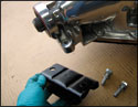
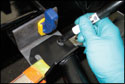
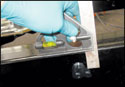
| 12. Mark where the holes on the ends of the crossmember are
on the “L” bracket and then mark some corresponding holes where
you want to drill to mount the “L” bracket to the frame. Remove
the clamps and the brackets and take the brackets to the bench. |
|
|
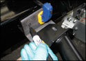
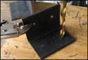
| 13. Drill the holes you marked in the “L” bracket.
Then bolt the “L” bracket to the crossmember. Mark the frame where
the holes on the “L” bracket are located making sure the engine/trans
assembly is still level and even between the frame rails. Then remove the
“L” bracket from the car. |
|
|
| 14. Drill the holes in the frame on the inside where the marks
from the “L” bracket are. Then, using a Mechanics Square measure
how far down from the top of the frame the holes are. Scribe a line on the
inside of the frame at each hole. Using your Square again place it on the
top of the frame and line the Square up with the line on the inside of the
frame. Scribe another line on the top of the frame. Then, line the Square
up with the line you scribed on the top of the frame and measure down from
the top the same amount as the dimension you had on the inside of the frame.
This is where you will drill the holes on the outside of the frame so your
bolt can come through to mount the “L” bracket. (If you are performing
this with the body on the frame make your measurements from the bottom of
the frame) |
|
|
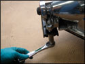
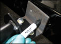
| 15. Drill the holes for the bolts on the outside of the frame
and reinstall the “L” brackets. Be careful when you tighten the
bolts holding the “L” bracket to the frame. Remember that if you
get too carried away you could bend the sides of the frame in. You are using
lock nuts, so they only have to be tight. If you are not using locknuts,
Locktite or a similar thread locker can be used here. |
 |
|
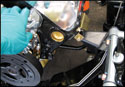
| 16. Now that the rear is secure you can turn your attention
to the side conversion brackets. Start by marking where the holes in the
brackets are on the frame. You should still be level and lined up properly. |
|
|
 |
| 17. Remove the engine and trans assembly and drill out the
holes where you marked them on the frame. If you are welding the mounts
in place leave the engine in the car at least until you have tacked the
mounts in place. You can completely weld them with the engine installed
if you prefer. |
|
| 18. Bolt the mounts to the frame. You may find that the mounts
do not fit flat on the frame. This is okay and will not affect the strength
or effectiveness. If you are welding the mounts in place you can add a shim
if you like, but this is not necessary. If you are bolting them in place
you can place shims between the mount and the frame as well, but this is
not necessary. Follow the instructions for the mounts in regard to the number
of bolts needed and their position. |
|
| 19. Bolt the assembly back in the chassis if you removed it
and you are done. If you have done everything correctly, a level placed
on the valve covers will show plumb and the engine and transmission assembly
will be sitting evenly between the frame rails. (A slight variance will
not cause any problems.) |
|
Note: Some fluctuation in where these components are installed
in each individual frame is to be expected. We provided dimensions that
came from the seamless frame we were working on. All frames differ somewhat
from each other and the seamed frame differs substantially from the seamless
frame. The key is to remember that the rivet we spoke about in the very
beginning of this article represents the common starting point for the installation.
Also, big block installations will require some modification of the firewall
to allow the big block to fit.
We hope we took some of the mystery out of doing this installation
and conversion. It looks complicated, but if you go slowly and follow these
instructions you should be able to do the job in your garage with a minimum
of problems.
Now where did we put that 502 with the Richmond 6-speed? |
|
 |
| It's always best to have shop and assembly manuals on hand
to make sure your installation is correct and to make the project as easy
as possible. We recommend factory manuals, available at Greg's
Automotive |
|
|
|