 |
| Classic Performance Products |
| Installing a C-4 Streetfighter Trans Package |
| By Grant Petersen |
|
|
|
| Most of us truckers are a "can-do" bunch who aren't
afraid to tackle the majority of things involved in building or maintaining
our pick 'em ups, but out of this bunch not too many of us are proficient
enough to build our own automatic transmissions, are we? It might be easy
enough to clean up a swap meet or junkyard tranny and put a new converter
and shift kit in it, but even then you don't know if you'll have to pull
it out in a month because it was shot to begin with. Well, it doesn't pay
to gamble with things of this nature. There are pros out there for a reason!
The professionals at CPP eat, breathe, and sleep ATF, and we can benefit
from their expertise by enjoying the end result of their hard work and engineering.
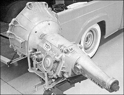
They have recently made it that much easier to get your tires spinning with
one of their Streetfighter transmission packages. This includes a triple
tested CPP tranny, a precision tuned CPP converter, 3 gallons of TO RTF
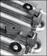
fluid, and a universal tranny cooler. |
The Streetfighter trannies are great for nor- mally aspirated
engines cranking out 450 horsepower on pump gas, and TO has them in many
different GM, Ford, and Chrysler configurations to suit your needs. Not
only do the TO trannies feature special clutches, bands, and improved lubrication
that brings up the line pressure, resulting in firmer shifts, but each unit
is blueprinted and dynoed before it leaves their building. It just
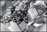
so happens the Smeding 392 Ford in the '60F-100 we've been working on registered
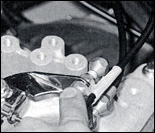
a cool 457 horsepower and needed a (-4 to transfer its ponies to the ground.
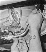
The manual/automatic valve body-equipped '72-80 large bellhousing (-4 we
received came ready to go minus a kickdown cable and a shift linkage, which
was easy enough to order from CPP. Since the F-100 had a mid-engine trans-mount
stock, we got a new tubular crossmember from Classic Performance Products. |
CPP's crossmember only needed four holes drilled into the
bottom of the frame and it was golden. The last thing we needed was a driveshaft,
which we ordered from Inland Empire Driveline. It was ready a few days later.
One thing we deviated from on the TO package was the use of a remote transmission
cooler and fan combo from Flex-a-lite. This would eliminate the need to
mount the cooler in a place to catch the wind so we could stick it easily
up under the truck. If you use an existing cooler, you'll need to back-flush
it to prevent contamination of the new system. Also, it's very important
to adjust the kickdown cable according to the directions to avoid the wrong
operating pressure under hard acceleration. It is also a good idea to start
the vehicle up on jack-stands until you confirm everything is adjusted correctly.
Follow along as we walk through all this shifty business! |
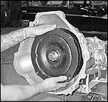 |
| 1..First things first don't forget to install the torque converter!
I know it's a simple step, but I have the attention span of a gnat. And
before that, top it off with fluid. Slide the converter onto the tranny
while turning it back and forth to seat it all the way into place. |
|
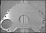 |
| 2..This simple piece of stamped sheetmetal seems to be somewhat
of a mystery. Not only does it act as a dust cover, but it also serves as
a spacer to keep the torque converter from pushing into the tranny too far
and damaging the whole shebang. We got this one from a local parts store,
but beware, there are at least three part numbers for a 351 to a C-4 application,
and we've yet to get to the bottom of it; not even the "seasoned"
parts guy at the dealership knew how to help us. If you don't have a stock
one and are so inclined, you can modify (cut up) one to work. |
|
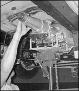 |
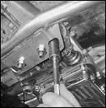
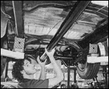
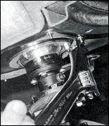
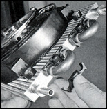
| 3..With the converter and spacer plate in place and the engine
supported, the trans is hoisted into its new home. A transmission jack pays
for itself at a time like this! |
|
 |
| 4..Classic Performance Products new tubular tranny crossmember
for us. Since it's made from tube, it's more ridged than the common bent
flat plate crossmembers, plus it has these clever holes to access the tranny
mount bolts on the tranny itself. |
|
 |
| 5..It would have been easier to install these studs in the
converter while it was out of the truck, but it was a little late at this
point. |
|
 |
| 6..Nonetheless, we got it handled and tightened the nuts that
hold the 164-tooth flywheel to the converter. |
|
 |
| 7..Now it's time to bolt the starter into place. |
|
 |
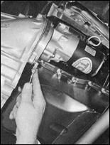
| 8..Just as you'd expect, CPP has whichever dipstick you might
need. This C-4 dates from '70-82, and has the dipstick that threads into
the passenger side of the pan versus the case. |
|
 |
| 9..Before filling the trans I called Inland Empire Driveline
in Corona, CA, and gave them the measurement from the face of the rearend
yoke to the face of the output shaft on the tranny, and they got started
making a new driveshaft. Since there are different yokes for 9-inch rearends,
they needed to know which one we had on our Currie assembly. It turned out
to be the heavy-duty 1 1/8 x 3 5/8-inch rear U-joint. With a little ATF
on the yoke to lube the seal, the new driveshaft went in nicely. |
|
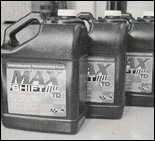 |
| 10..Included in the Streetfighter package are 3 gallons of
Max Shift RTF. The Max Shift fluid has been tested to run up to 30 degrees
cooler than regular ATF even under harsh conditions, which will help any
transmission live much longer. To start out, add 4 quarts to the trans,
and with the vehicle on jackstands, fill the rest as needed while it's running. |
|
 |
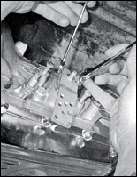
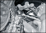
| 11..But first, we need to be able to grab the gears! CPP provides
the means to hook just about anything up to whatever you might need, and
they had just the ticket to connect the C-4 to the shift linkage on the
ididit steering column. |
|
 |
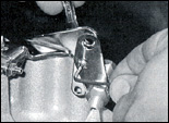
| 12..The C-4 was sent out with a universal shift arm on it,
but that was ditched in favor of the CPP unit. |
|
 |
| 13..The directions told me that with the trans in park the
new arm should be in the 8 o'clock position. |
|
 |
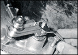
| 14..With both the column shifter and trans in park, it was
plain to see the stainless rod was too long and would need to be cut down
so both set screws intersect the rod. |
|
 |
| 15..Once bolted the place, the up and down angle of the rod
end and stainless rod off the column was too severe and maxed out the rod
end's pivot, misaligning the linkage to the trans. |
|
 |
| 16..A slight counterclockwise tweak with a big adjustable
wrench on the shift lever off the column made things line up much better.
Now the rod end at the column isn't maxed out. |
|
 |
| 17..After cutting the stainless rod to length with a hacksaw,
I marked the spots where the set screws would hit it and ground flat spots
in the rod about 3/16- inch deep so they could do their job. |
|
 |
| 18..Grinding the flat spots for the set screws is necessary
since this kit is universal and cut to fit. Once that's taken care of, a
little bit of thread lock does the trick before the set screws are tightened
down. |
|
 |
| 19..Tada! Notice the bend in the rod I did that to align the
rod end at the tranny because it was being pulled too far to the left. I
jumped inside the truck, shifted through the gears, and got all positive
clicks! |
|
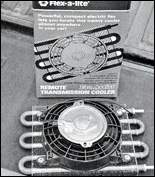 |
| 20..Now we needed a way to keep the tranny cool. We opted
for this Flex-a-lite unit (PN 4190) with its own electric fan so it can
be stuck somewhere out of the wind and still work. |
|
 |
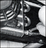
| 21..Flex-a-lite supplies mounting hardware to mount the cooler
just about anywhere. These plastic brackets go on both sides of the copper
tubes and use through bolts to mount to the frame or any flat surface. Don't
worry, it can be mounted to a radiator as well. |
|
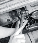 |
| 22..We chose a spot out of the way of exhaust, plumbing, and
road debris, which wound up being on the outside of the passenger side framerail
just behind the doorsill. Using a transfer punch makes marking the holes
much easier and eliminates curse words. |
|
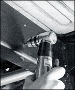 |
| 23..Here you can see the nice flat area of the frame we're
mounting it to. A right angle drill came in handy here with the doorsill
blocking the use of our other drill. |
|
 |
| 24..These provided rubber spacers not only facilitate an air
gap between the cooler and its mounting surface, but they help isolate it
from vibrations as well. |
|
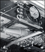 |
| 25..It's nice to be able to mount the Flex-a-lite trans cooler
this close to the trans, eliminating the need for long cooler lines snaking
through the framerails. |
|
 |
| 26..Flex-a-lite even provides the hose clamps for the 5/16-inch
rubber hose (not provided). All that's left is to hook up the power and
ground, which will probably be routed to a keyed source instead of a toggle
switch to eliminate the possibility of forgeting to turn the fan on. |
|
 |
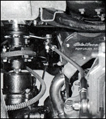
| 27..CPP had the rest of what we needed to help make the drivetrain
operable, like their C-4 Hi-Tech kickdown kit, stainless steel throttle
cable bracket and the rest of the throttle components, which we'll get to
later. |
|
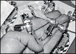 |
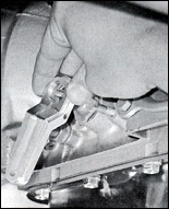
| 28..The kickdown kit looks tricky, but it boils down pretty
easily once you start hooking it up. The end on the right goes to the carburetor,
while the left side goes down to the transmission. |
|
 |
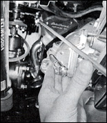
| 29..I started by installing the throttle cable bracket, which
goes on the rear carburetor mounting stud like so. |
|
 |
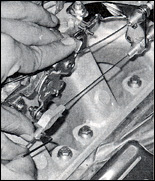
| 30..The kickdown cable has a small tab that connects it to
the throttle cable bracket with a single stainless button-head Allen screw. |
|
 |
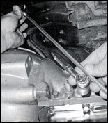
| 31..With the kickdown cable anchored up top, it's time to
go underneath again. First, take off the nut that holds the aluminum shift
arm to the trans, slide on this kickdown lever, and reinstall and tighten
the nut. |
|
 |
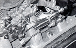
| 32..The bracket that holds the cable housing to the trans
goes on without a struggle. |
|
 |
| 33..After sliding the inner cable out of the housing, the
housing was routed in its final state to the throttle cable bracket and
marked to be cut. If you are in doubt if you have enough slack in the housing,
it's safe to add an inch before cutting it with cable cutters, a fine-tooth
hacksaw, or a cut-off wheel. If you don't have the tools or don't want to
buy them, a bicycle shop could probably cut the housing and cable for you. |
|
 |
| 34..Next, the slide fitting is bolted to the Carb linkage. |
|
 |
| 35..Feed the cable back through the housing and the slide
fitting and install the small barrel-shaped cable stop with a set screw
in the middle of it. Before finishing, make sure the aluminum cable adjuster
at the throttle cable bracket is adjusted in the middle of its threads to
allow for tuning either way later. With one hand holding the throttle wide
open, pull the cable as tight as possible, anti with the cable stop up against
the slide fitting, tighten the set screw. It'll help to barely tighten the
set screw against the cable to hold the stop in place while all this is
going on. Either that, or get your significant other out in the garage to
lend a hand. |
|
 |
| 36..With the throttle back at idle, the cable stop is off
the slide fitting just under an inch or so, making it engage the kickdown
only when you put the pedal to the metal! |
|
|
|