 |
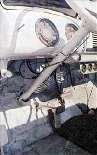
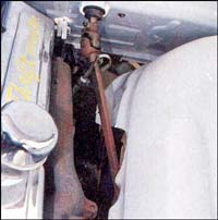
| 1. Our early-'50s ice cream truck is low but slow to steer.
Here's the original steering column that runs into the recirculating ball-screw
steering box. It takes a lot of muscle to turn the wheels, especially at
a stop, even with the large steering wheel. We'll fix it to turn as smooth
as melted ice cream. |
|
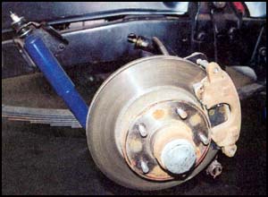 |
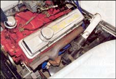
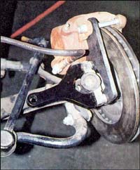
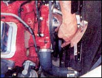
| 2. Our ice cream truck already has a Classic Performance Products
disc brake conversion kit and is low enough to suit our tastes. It just
needs to steer smoother and easier, and it will soon. Note the position
of the front shock. We planned to relocate the top mount rearward for clearance. |
|
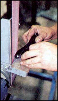
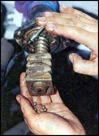 |
| 3. It was interesting to pull the old steering box off the
end of the column to see how the small steel recirculating balls were packed
in grease inside the box. |
|
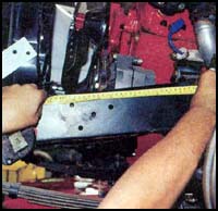 |
| 4. The old box was removed and the driver-side shock mount
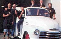
was also removed. It was now time to locate the new Saginaw box. From the
center- line of the front axle, we measured 12-1/2 inches forward on the
framerail. |
|
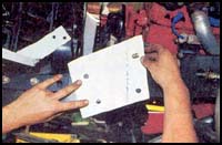 |
| 5. To mount the new box, we needed to use the two existing
holes in the framerail, with one new hole drilled in the framerail sidewall.
We also planned to weld a small triangular tab with a mounting hole to the
top surface of the framerail near the edge. This paper template helps us
locate the new hole precisely where it needs to be. |
|
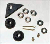 |
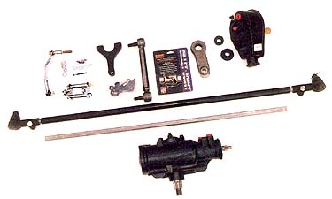
| 6. The Classic Performance Products kit supplies the hardware
to mount the new Saginaw steering box. The small triangle was welded to
the top surface of the framerail on the driver side. There are four aluminum
spacers; one is slightly larger and is used with the welded triangle tab
bolt. |
|
 |
| 7. Classic Performance Products also supplies a new pitman
arm and steering arm with this kit, as well as an adjustable drag centerlink.
We tried to maintain the alignment by keeping everything in place. |
|
 |
| 8. The new steering arm needed just a little bit of grinding
of a corner to clear the disc brake caliper. After a little grinding, it
was mounted to the spindle. Notice that we cut off the old steering arm
just below the new steering arm. We had to shape and paint the raw end to
look nice and neat. |
|
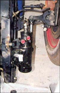 |
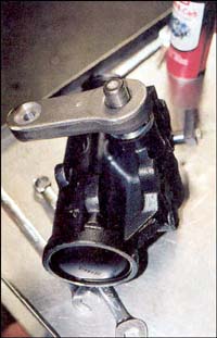
| 9. Here's a good shot looking straight down on the Saginaw
box. Notice the welded triangle and the spacer on the bolt that goes through
it. The steering shaft gets installed to the Borgeson universal joint shortly. |
|
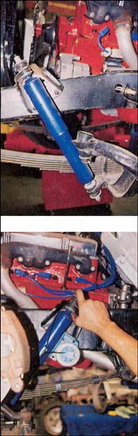 |
| 10. As we mentioned earlier, the top shock mount has to be
relocated to the rear of the axle. We used an angle finder to duplicate
the angle of the shock in its new position, drilled holes, and bolted it
in place. |
|
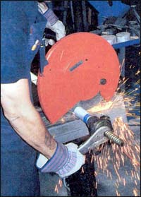 |
| 11. To make the original steering column work with the new
Saginaw box, it was necessary to modify the bottom end of the column. The
first order of business was to cut off the old, worn gear end. |
|
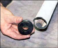 |
| 12. We planned to modify the bottom end of the original column
by adding this Teflon spacer to the inside of the column housing and around
the outside of the inner steering shaft. But first there were a couple of
custom operations to be performed. |
|
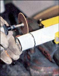 |
| 13. We first needed to trim 2 inches off the outer tubing
to expose the round steel inner shaft. |
|
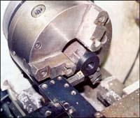 |
| 14. Just a little lathe work was needed to reduce the diameter
of the Teflon spacer to match the inner diameter of the outer tube. We wanted
a press-fit, so we checked it carefully to make sure it didn't get too small.
Yeah, it would have been somewhat easier to install a more modern column,
but we wanted to retain the original steering wheel and small-diameter column
to keep a vintage appearance. |
|
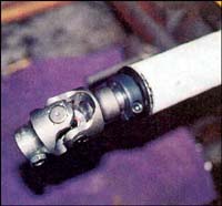 |
| 15. Here's how the bottom end of the column looks with the
Teflon spacer located inside the column tubing. The steel inner shaft was
now connected to a Borgeson universal unit and a locking collar was located
in between to keep the Teflon spacer in place. |
|
 |
| 16. Just a couple of little details and this install will
look like it came from the factory. One of Wheeler's Shop staff made a nifty
column drop that later allowed the column to be bolted to the underside
of the dash. |
|
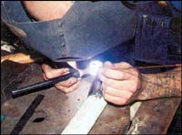 |
| 17. After removing the original steering box, the bottom of
the steering column needed some additional support on the toeboard. We made
a small angle-brace with a bolthole and welded it to the outer tube. |
|
 |
| 18. With the column drop and the angle-brace painted and in
place, everything looked as if it were originally designed this way. Now
we'll hook up the steering at the bottom end of the column. |
|
 |
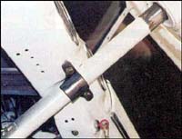
| 19. We used a section of steel D-shaft between two Borgeson
universal joints to connect the original column with the Saginaw box. A
little trimming of the inner fender panel was required to clear the D-shaft. |
|
 |
| 20. One more little custom modification was required, none
of the double pulleys for Chevrolet allowed the power steering belt to align
properly with the pump. We added a single pulley to the original pulley
to arrive at the proper position for the new power-steering pump belt. The
reservoir was bolted to the front of the small-block and all the steering
hoses were attached. Soon we were ready for a test drive. |
|
 |
| 21. Hey, it works great! Here's the crew at Wheeler's enjoying
a taste of ice cream and the smooth Classic Performance power steering of
our vintage Chevy ice cream truck. |
|
|