| Classic Performance Products |
| Installing a Master Cylinder and Power Brake
Assembly |
| By Jeff Tann |
|
|
| Whoa power is as important as go power in any street rod,
and today most street rods are equipped with disc brakes so they can slow
down just as quickly as the car in front of them. Safety should be a concern
to anyone building a street rod or street machine, and having excellent
brakes is not just a good idea but should be mandatory as well. This street
rod, a '35 Ford, will be equipped with Wilwood front disc brakes and Chevy
rear drum brakes, and a top-quality master cylinder with power assist was
required. |
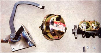
The owner decided to equip the '35 Ford chassis with a bolt-in
master cylinder and power booster kit from Classic Performance Products
(CPP). The master cylinder is a brand-new item cast by the company specifically
for street rods and street machines. One was ordered that works perfectly
with the disc/drum setup used on this car. If you are building a chassis,
this master cylinder, power booster and pedal kit is easy to install and
should take only a few hours to complete if you don't figure in the time
it takes to hook up the brake lines. |
The installation is easy, but you will need a metal-cutting
device, such as a 3-inch cutoff wheel or a plasma cutter. The rest of the
installation will require an electric drill and various hand tools. If you
are working on a '35-'40 Ford and plan to hook up a master cylinder, follow
along and we'll show you how easy it is. |
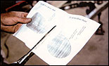 |
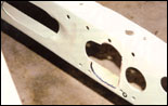
| 1) The brake pedal assembly comes with a template for the
installation. We cut out the template, punched the holes for the bolts and
located the proper position for the template on the framerail crossmember. |
|
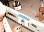 |
| 2) The template was traced on the crossmember. We found that
three of the bolt holes line up to existing holes and only one will have
to be installed. |
|
 |
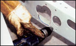
| 3) The new hole in the crossmember was cut out with a plasma
cutter. This could also be done with a 3-inch cutoff wheel, but it wouldn't
be as precise and would be a slower process. |
|
 |
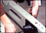
| 4) A close look reveals the nice, clean cut that the plasma
cutter made. Only minor sanding will be required to get it perfect. Notice
that three of the bolt holes are already in the frame, but one will have
to be installed. |
|
 |
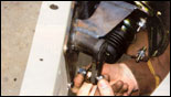
| 5) Following the mark made on the frame, the bolt hole was
drilled with an electric drill motor and a small step drill. |
|
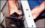 |
| 6) Using the kit's button-head Allen bolts, the brake bracket
was bolted on the crossmember. Here, they are installed finger-tight. |
|
 |
| 7) After the bolts were installed, they were tightened with
an Allen wrench and a 1/2-inch open-end wrench. |
|
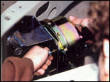 |
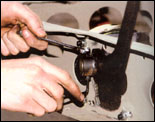
| 8) The vacuum booster was installed next and secured with
the nuts supplied in the kit. The booster looks great with the gold-cad
finish. |
|
 |
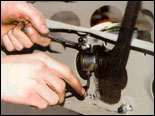
| 9) The pedal shaft was installed through the boss in the bracket.
It's a good idea to lubricate the shaft before it is permanently installed. |
|
 |
| 10) The female Heim joint end was installed on the booster
drive rod. |
|
 |
| 11) The pedal was installed over the shaft assembly and then
the securing bolt was tightened with an Allen wrench and box-end wrench. |
|
 |
| 12) The booster assembly was connected to the power booster
with the bolt and locknut supplied in the kit. |
|
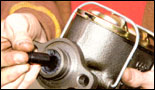 |
| 13) The master cylinder was equipped with the small drive
fod that was supplied in the kit. Notice that it was lubricated before it
was installed. |
|
 |
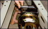
| 14) The master cylinder was installed on the two studs in
the power booster and then the 9/16-inch bolts were installed finger-tight. |
|
 |
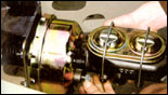
| 15) The bolts were secured with a large 9/16-inch box-end
wrench. The master cylinder cap is also gold-cad-plated, and together the
booster and master cylinder look terrific. If you look closely, you can
also see the black vacuum fitting in the booster. |
|
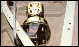 |
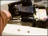
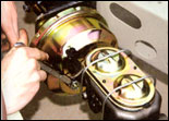
| 16) Here is the booster and master cylinder assembly mounted
in the '35 frame and ready to plumb. The assembly fits great and the pedal
assembly is in the same place as the original. |
|
|
|