 |
|
|
|
|
|
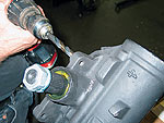
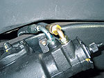
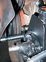
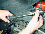
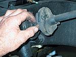 The manual box was still in decent condition, as far as 40-year-old trucks go, but my arms were ready for an upgrade. Alan began by removing the rag joint that attaches the steering shaft to the box. Next, the center link was pried off of the pitman arm. |
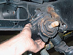 After buzzing off the mounting bolts, the stock box was removed from the framerail. |
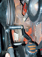
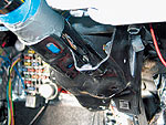
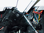 The column mount in the '60-66 trucks also houses the brake-light switch and stop for the brake pedal, as well as the E-brake assembly. The bolts were removed and the mount came off, allowing the column to hang free. | ||
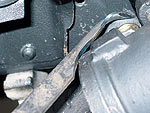
 In the engine compartment, this bracket bolts to the firewall and clamps to the column. It was removed next. At this point, we could have simply removed the inside cover that surrounds the column on the inside of the firewall and slid the entire unit out, but I buried it in Dynamat insulation a few months back! We opted to tear down the column a bit more so it would slide though the cover instead. |
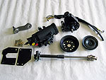
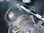
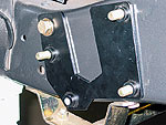
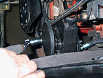
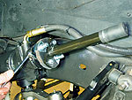
 With the old column removed we could start the upgrade. Power steering wasn't an option until the '68 model year, and the factory had to dimple the frame to make room for the larger box. A power steering box can't just be bolted to a non-dimpled frame. One solution is to try and heat the framerail and dimple it yourself, or a much easier and safer method is to use this mounting plate from CPP. The mounting brackets were test-fit to the framerail by using two of the existing holes before drilling the other two. |
 For this particular kit, one of the threaded holes of the power steering box needed to be drilled out as per the directions. | ||
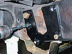
 After cleaning and painting the area, the brackets were mounted up permanently. |
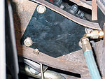 The inner plate supplied by CPP adds a ton of much-needed strength and support to this area of the frame (which is prone to cracking on the trucks that used this box) |
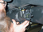 The box was set into place and tightened down. | ||
 Alan attached the new pitman arm and rotated it to center before the center link was reattached. Both the pressure and return lines were then routed between the frame and the inner fender without any modifications. |
 On this application, part of the bumper bracket had to be trimmed to clear the new box. |
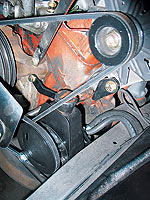
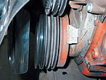 Moving on to the power steering pump, Alan added a third pulley to the crank pulley to run the pump. | ||
 Alan hung all of the mounting brackets from the power steering pump first, and then attached the pressure and return hose. |
 The lower bracket attaches using the two holes in the block near the crank pulley. |
 The adjustment bracket attaches to the lower water pump bolt. | ||
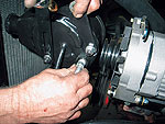
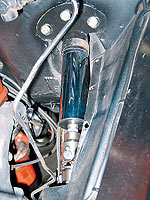
 Alan then attached the pulley and hung the belt. The belt was adjusted from the stud on the back of the pump (see arrow). |
 It's a tight fit down near the framerail, but the bracketry positioned the pump in the ideal spot and left room for adjustment. One problem we did run into, though, was that once the pump was mounted, it interfered with the alternator belt. We fixed this by installing a double-groove pulley on the alternator, which moved the belt out slightly so it could now run off the second groove on the crank. |
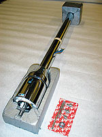
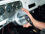
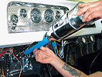 We were now ready to start on the new ididit column. We taped up the column to keep it from getting scratched during installation. There are a few inches of play regarding where you want the column mounted. But since I'm a fairly large guy, we pushed it as far through the floor as possible. | ||
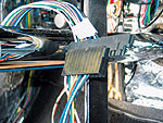 The ididit column uses a standard GM 3 7/8-inch connector that attached directly to the Painless wiring harness. Several adapters are also available to make most trucks a simple plug-in. |
 We cleaned and painted the column mount and reinstalled it. The column was pretty secure as is, but ididit recommends that you use two short set screws through the mount into the column. |
 Alan attached the intermediate shaft to the new rag joint and secured it to the input shaft on the box. | ||
 The stainless Double-D shaft with the universal joint coupler attached was slid into place. |
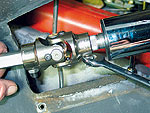 This universal joint coupler fits a Double-D shaft on one end and splines on the other, making this a simple bolt-on affair. If you choose to run a splined shaft, you will need to know the exact measurements beforehand. |
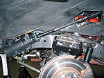 This under-fender shot shows a clean and simple setup that will offer years of trouble-free steering. | ||
 On the firewall, the clamp was reattached to the column, and the bracket was bolted back to the firewall. |
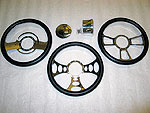
 Before bolting on the adapter and steering wheel, we installed the hazard knob and the tilt and turn-signal levers. Alan then set the adapter into place and snugged it down. |
 The chrome wheel was mounted up next, and the center cap even covers the Allen head bolts. I never imagined what a difference a column and steering wheel could make to the overall appearance of the cab! And my arms don't hurt after maneuvering through car shows or parking lots anymore! | ||
 |
|
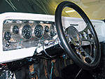
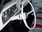 Before
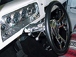 After
After