1.) The first step in the removal of the steering column
is to remove the steering wheel and horn assembly. Remove the horn ring
cap and horn ring by removing the three Phillips head screws that secure
it. Now you want to note the position of the pieces for re-assembly later.
Note: On Belair models the horn ring cap is retained either by a clutch
head style screw which is removed from the under side of the steering wheel
or clips.
2.) Now using the ratchet, extension and 3/4" socket,
remove the retaining nut that secures the steering wheel.

3.) With the help of a steering wheel puller you can now
remove the steering wheel.
4.) With the wheel off you should now remove the spring
and spring seat from the end of the shaft.
5.) Remove the shifter arm by driving the pin out using
the ball peen hammer and 3/16" punch.

The spring on the ball end of the lever needs to be removed
and retained.
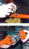
6.) Remove the neutral safety switch by first pulling
the wires, noting the connector positions for re-assembly, then using the
Phillips head screwdriver remove both retaining screws. The switch fastener
ears are slotted to allow for adjustment during re-assembly.

7.) Disconnect the turn signal/horn wiring harness located
on the left side of the column under the dash.
8.) On 55-56 vehicles, slide the rubber seal up far enough
to allow you to get at the clutch head screw retaining the lower cover.
9.) Remove clutch head screw and lower cover.
|
10.) Remove upper cover using a medium sized fiat head
screwdriver to carefully pry off (it's retained with spring clips).
11.) Remove the shift indicator wire by unhooking the
wire from the indicator needle assembly and the steering column wire loop.

12.) Remove the inside steering column clamp by removing
the two bolts using your 1/2" socket with a small extension. Be sure
to inspect the rubber shim/insulator for damage or wear prior to reassembly.
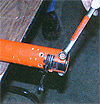
13.) From under the hood, disconnect the transmission
shift linkage rod at the steering column shift arm using a 1/2" wrench.
Also remove the shifter arm detent from the bottom of the column using a
3/8" deep socket.

14.) Disconnect and remove the lower clamp by removing
the two bolts securing it with your 1/2" wrench and socket. The upper
bolt must come out entirely. Slide the clamp down the housing and rest it
on the steering box.
15.) Using your dikes, clip off the protruding portion
of the clips securing the steering column floor seal and push them through
the firewall using the 3/16" punch and hammer needed. The column assembly
should be ready to come out.
STEERING BOX REMOVAL

1. Remove the 1-1/4" nut and washer that secure the
pitman arm to the sector shaft.
2. Using the pitman arm puller, remove the pitman arm
from the sector shaft.
3. Remove the three nuts securing the steering box to
the frame (9/6").
4. Remove the box by wiggling it off the frame then carefully
moving it up and out. If the generator Is in the way you may need to either
loosen it and move it in or take it out completely.
|
605 STEERING BOX INSTALLATION
Our modified box makes this extremely easy.
1. Bolt on box in the stock position.
2. Re-install the pitman arm on the sector shaft.
3.) Install the new rag joint on the steering box. If
all has been successful you should now be ready for the bench work.
BENCH WORK

The first step is to separate the column mast jacket from
the shifter tube.
1.) Using your Phillips head screwdriver, disassemble
the upper end of the column by removing the three retaining ring screws
from the lock plate. One of the screws has no obstructions but you will
have to move the turn signal in one direction or the other to remove the
other two.
2.) Remove the wire retainer clamp by unscrewing the retaining
screw on the left side of the column at the entry slot.
3.) Remove the wires from the retainer with a small flat
head screwdriver. Note: Be sure to mark exact location of each wire.

4.) Remove the turn signal housing by pulling the entire
assembly out through the top taking care not to damage any wiring or connectors.
1. Remove the lock plate, spacer and shift lever housing.
2. Disassemble the lower portion of the column by removing
the three bolts and washers, using a
1/2" socket or wrench, then carefully removing the
lower bearing.

7.) You should now be ready to separate the shifter tube
from the steering column and clean both parts. We are now ready for the
tube and steering column modification.
|
 |
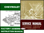
| It's always best to have shop and assembly manuals on hand
to make sure your installation is correct and to make the project as easy
as possible. We recommend factory manuals, available at Greg's
Automotive |
|