Power Steering 1947-1959 Chevy and 1948-1956 Ford pickup
trucks
|
|
 |
|
- Classic Performance Products
- Adds Power Steering to your
- '47-'59 Chevy or GMCTrucks
|
In the July 1993 issue of Truckin' magazine, we
printed a story called "Power Piloting For Old Chevys" which
focused upon a trick new power steering kit for 1947-'59 Chevy truck owners.
The kit is manufactured and offered from Classic Performance Products and
is designed to be used with any old GM truck, but especially the resto
buffs. Well, Classic Performance
Products have another power steering kit as well, but this kit is more
for the serious customizer who is building a tricked-out ride. The kit
uses a late model GM Saginaw power steering box and pitman arm, a late
model steering column, and the new drag link, steering arm and other products
provided in the kit. The process involves first removing our stock
steering column and box assembly, then replacing the steering column with
a late model unit (not included in the kit), preferably from a '70s or'80s
Chevy van. Then, the stock shock bracket riveted to the frame is
removed and reinstalled aft of the axle on the frame, thus relocating the
shock.
|
A GM Saginaw power steering gear box (not included
in the kit) is attached to the frame using the dimensions provided in the
instructions. The kit comes with three spacers that position the steering
box appropriately away from the frame and a bracket that is to be welded
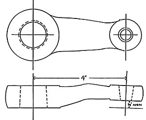
onto the frame. Also, you will need to acquire a pitman arm that is 6-3/4
inches long. An El Camino or Chevelle has an arm that works well.
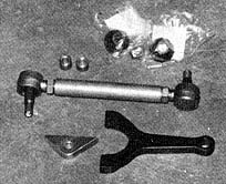
The Classic Performance Products kit also includes a replacement steering
arm that is mounted to the brake backing plate, with an adiustable drag
link being attached at the pitman arm on one side, and to the steering
arm at the other end. The last focal point is the steering shaft which
must be constructed using Borgeson joints and 3/4-inch mild carbon steel
intermediate shaft. Attach the Borgeson joints to both the steering column
and to the steering box, then measure the distance, cut and weld the joints
onto the shaft, making sure that the joints are in time.
|
This power steering installation isn't very hard to accomplish
and is more of a custom approach to installing power steering versus the
first power steering story we showed in the July issue. Both kits work
great, and now you have the option of choosing either or to get the job
done as you like.
Note:
Installation Correction
1. On all years drill 3/8" hole
12-1/2" from center line of axle towards front of vehicle and down
1" from top of framerail. Note: (1947-54 do not use brake line hole
as reference.
2. Lower shock brackets are flipped
front to back, not left to right. The lower shock bracket will be angled
upward allowing clearance for the tie-rod. |
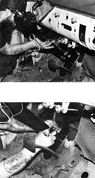
Now we move down to the chassis which has already been
jacked-up and properly supported, with the wheels, stock drag link and
brake drums removed. Remove the shock from the top mount and remove the
lower shock mount entirely. The driver's side lower bracket will be mounted
on the passenger side and vice-versa, from the back side.
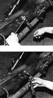
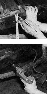
The shock mount on the frame must be removed. The mount
is riveted into place, so a chisel and hammer are the only way to break
the mount loose.
|
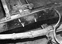
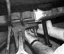
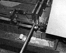
In the instructions, the exact location of the shock
bracket is shown, but in this photo, you can see how one hole on the frame
is utilized, while two others must be located and drilled. The shock mounting
pin should sit right over the hole where the old pitman arm was mounted.
When the other two holes are drilled, the shock bracket
is firmly mounted.
Now, the rivets that you chiseled off will obviously
still be in the frame. Use a hammer and center punch to totally remove
the rivets and clear the holes.
|
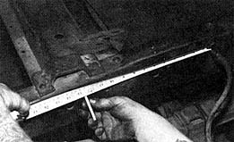
Take a tape measure and put the end on the brake line
extending through the frame. From that point, measure out 12-1/2 inches
along the top of the frame and mark. (12-1/2 inches from center brake line
hole to new mark on frame)
From that mark you just made at 12-1/2 inches, measure
down one inch and mark. This is where you will drill an additional 3/8
inch steering box mounting hole.
|
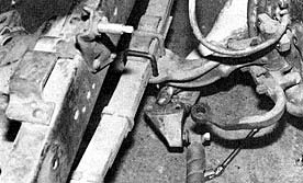
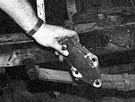
The kit provides a triangular bracket that attaches to
the Saginaw steering box. This bracket holds the box in place on the frame
which will be welded.

Using the hole you just drilled and the frame bracket
attached to the steering box, mark the two lower holes.
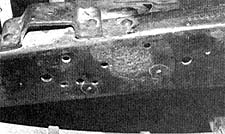
Here you can see the two holes to be drilled.
|
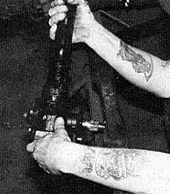
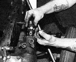
Once the holes have all been drilled, the provided bolts
and spacers are inserted from the inside of the frame outward with the
spacers on the outside of the frame.
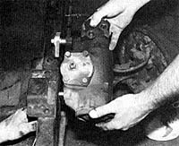
Have someone hold the power steering box in place while
you tighten the bolts, securing the box to the frame.
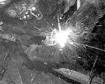
When the steering box has been bolted in place securely,
weld the triangular bracket to the frame.
|
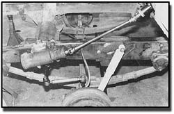
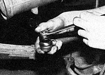
Next comes the installation of the new steering arm that
is bolted to the axle and backing plate via the two upper assembly bolts.
The factory steering arm that you see curving inward can either be cut
down or left alone.
Now reconnect the tie-rod ends to the axle on both sides
of the truck. As long as you didn't mess with the revolutions of the tie-rod
ends, the alignment will be fine.
To install the shocks, the lower mounting bracket from
the opposite side is used so that the shock can now be mounted behind the
axle instead of in front.
|
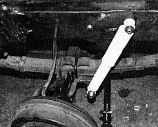 This is how the shock will look when installed
properly. This is how the shock will look when installed
properly.
While you are out in the junkyard, you must get yourself
a GM Pitman arm that measures 6-3/4 inches long. A Chevelle or El Camino
version will work and in some cases, you may have to drill out the drag
link end to accept the thickness of rod end on the drag link.
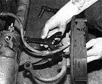
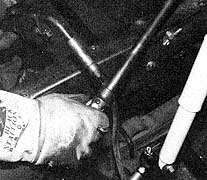
Install the provided Zerk fittings into the rod ends
of the drag link.
|
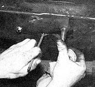
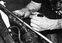
The drag link is installed from the bottom side of the
Pitman arm and secured in place with a cotter pin. The same goes for the
other end of the drag link that connects from the underside of the new
steering arm.
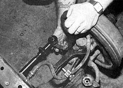
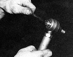
Now, install a Borgeson joint onto the output shaft of
the steering box.
Insert the bar stock end into the upper Borgeson joint
on the steering column and mark the desired length in relation to where
the end of the intermediate shaft should be when installed into the joint.
Shaft should be made from mild carbon steel.
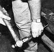
Either a bandsaw or a hacksaw will work to cut the Intermediate
shaft.
|
With both ends of the intermediate shaft installed properly
into the Borgeson joints, time the joints. Joints on an intermediate shaft
should be aligned so the ears of the yokes on that shaft are in line, not
90-degrees out of phase. It should be the same as a driveshaft. Then weld
the intermediate shaft and the joints together.
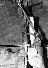
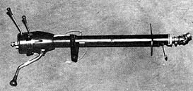
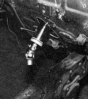
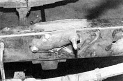
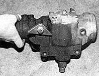
This is what the steering box will look like installed
with the steering shaft attached.
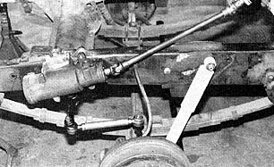
When you are done, this is what the assembly should look
like. The only thing to do is to install the power steering pump and lines
when you install the engine. Note: the Borgeson Joints are not in phase
in this photo. But they were put into phase before they were welded.
|
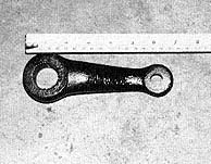
NOTE:
Locating the correct size pitman arm can be very difficult.
You can take any pitman arm that fits the steering box and which has the
correct hole size for the drag link, and have it shortened. We recommend
that you have it shortened and re-welded by a certified welding shop! Or
for your convenience, a a shortened and re-welded pitman is also available
from us.
|
|
| Classic Performance Products 378 E Orangethorpe
Ave., Placentia CA 92870 Tech Line 714-522-2000 |
 |
TECH
| BOOKS | SUSPENSION
| BRAKES | STEERING | CONTACT
US | HOT PRODUCTS |

|
| © Classic Performance Products. This "website"
and all contents are property of Classic Performance Products.
Prices subject to change without notice. Not responsible for
errors or omissions. Please note that kits & prices
may vary between certain applications. |
|
|
|
|
|
|
|