Classic Performance Products 175 East Freedom Avenue Anaheim, CA 92801

1928-32 Rear 4-Link Instructions


MODEL "A" TRIANGULATED 4-LINK

Frame should be boxed at least 4" on either side of the front frame bracket mounting area.
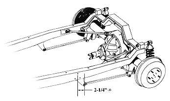
   A Center of hole in front frame bracket is located 2-1/4" behind the center of the top running board bracket mounting hole. Bracket is mounted flush with bottom of frame.
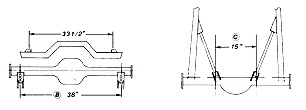
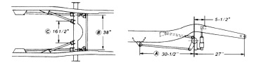
B Rear axle brackets are located 38" apart measured from center to center at the coil-over mounting holes. Make sure that both brackets are the same distance from the end of the axis housing. Position the front face of the axle housing parallel to the back face of the axle brackets.
Bars are assembled with adjusters at front.
C install angle brackets on adjuster end of short bar and housing tabs on opposite end. Housing tabs are located 15" from center to center. Angle brackets may require slight trimming for correct fit. Check for floor pan clearance before final welding.
Brackets should be tack welded and the assembly should be checked for square and alignment before final welding.
All welding should be performed by a qualified welder.
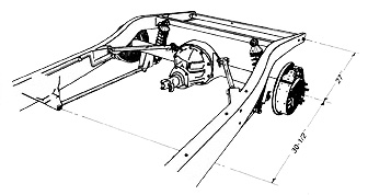
Please note - Kit is shown installed on our Model 'A' chassis with tubular crossmember and kick-up. All measurements also apply to stock Model 'A' chassis.
Coil-over shocks and mounting hardware are optional.


'32 TRIANGULATED 4-LINK

   A Center of hole in front bracket is located 30-1/2" forward of axis housing center. Bracket is positioned on inside of boxed frame rail flush with the bottom with the ears facing up. Frame brackets may need slight trimming to fit flush.
B Rear axle brackets are located 38" apart measured from center to cents at the coil-over mounting holes. Make sure that both brackets are the same distance from the end of the axle housing. Position the front face of the axle housing parallel to the back face of the axle brackets
C Install angle brackets on adjuster end of short bar and housing tabs on opposite end. Housing tabs are located 16-1/2" from center to center. Angle brackets may require slight trimming for correct fit. Check for floor pan clearance before final welding.
Coil-Over shocks and mounting hardware are optional
Bars are assembled with adjusters at front
Brackets should be tack welded and the assembly should be checked for square and alignment before final welding. All welding should be performed by a qualified welder.


© Classic Performance Products Inc.

This "website" and all contents are property of Classic Performance Products Inc. Disclaimer

 HOME ORDER TECH  BOOKS STEERING BRAKES SUSPENSION POLICIES